G046
User´s Guide
P
c
=
K
ø
D
c
2
n
(
0.647
+
17.29
f
)
×10
-6
(
kW
)
(
N
)
M
c
=
(
N
·
m
)
K
ø
D
c
2
(
0.630
+
16.84
f
)
100
T
c
=570
K
ø
D
c
f
0.85
210
21
177
1.00
280
28
198
1.39
350
35
224
1.88
250
25
100
1.01
550
55
160
2.22
620
62
183
1.42
630
63
197
1.45
690
69
174
2.02
630
63
167
1.62
770
77
229
2.10
940
94
269
2.41
750
75
212
2.12
1,400
140
390
3.44
580
58
174
2.08
800
80
255
2.22
User ’s
Gu ide-
Techn i ca l Reference
Material
constant
(
K
)
Brinell
hardness
(HB)
Kgf/mm
2
Tensile strength
Workpiece material
Cast iron
Cast iron
Cast iron
Aluminium
Low carbon steel (JIS S20C)
Free cutting steel (JIS SUM32)
Manganese steel (JIS SMn438)
Nickel chromium steel (JIS SNC236)
4115 steel Cr0.5, Mo0.11, Mn0.8
Chromium molybdenum steel
(JIS SCM430)
Chromium molybdenum steel
(JIS SCM440)
Nickel chromium molybdenum steel
(JIS SNCM420)
Nickel chromium molybdenum steel
(JIS SNCM625)
Chromium vanadium steel
Cr0.6, Mn0.6, V0.12
Cr0.8, Mn0.8, V0.1
Torque
Thrust force
Power requirement
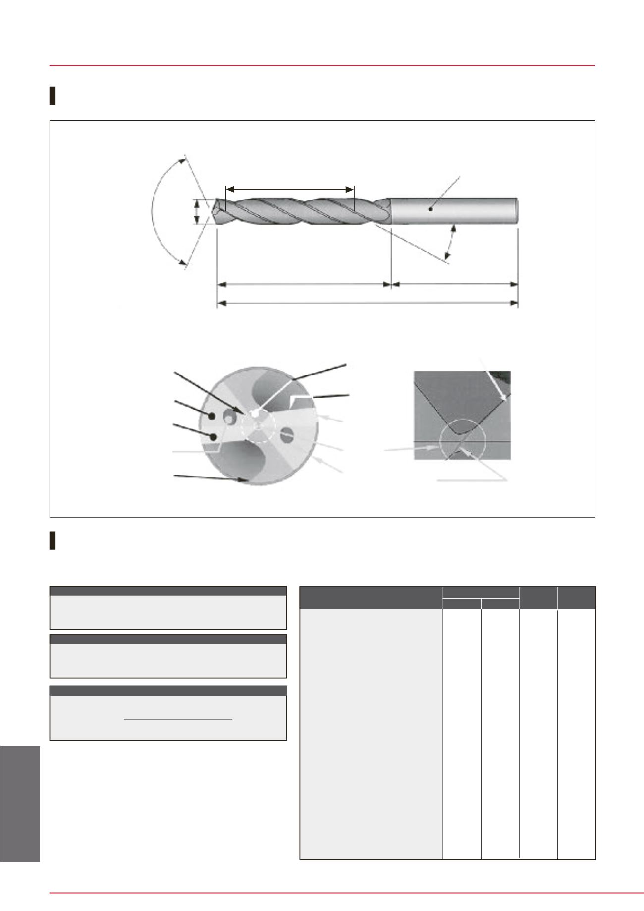
Nomenc l ature for sol id carbide dr il l s
Cut t ing forces and power requi rement
Twist drill
P
c
: Power requirement (kW)
T
c
: Thrust force (N)
M
c
: Torque (N·m)
øD
c
: Drill diameter (mm)
f
: Feed (mm/rev)
n
: No. of revolutions (min
-1
)
K
: Material constant .... Refer to the Table at right
Material constant compensating for power requirement and thrust force
Point angle Diameter
Lead
Shank
Helix angle
Flute length
Shank length
Overall length
Web thickness
Secondary relief
Primary relief
Oil hole
Heel
Thinning
Cutting edge
Margin
Chisel
Body clearance
Thinning edge
Chisel edge
Primary relief
Secondary
relief
Thinning
MPa (N/mm
2
)
Dr i l l ing Tool s


