G055
User´s Guide
Tungaloy
User ’s
Gu ide-
Techn i ca l Reference
Problem
Cause
Countermeasure
Machine
Clamping the workpiece is unstable.
Clamp the workpiece firmly.
The guide bush is apart from the
workpiece surface at the entry.
Contact the guide bush closely with the
workpiece.
The machine's rapid feed is used.
Use cutting feed.
Whipping e ect occurs.
Place a whip guide at the appropriate
position.
The shape of the guide bush is not
suitable.
Use the guide bush in the shape suitable for
the workpiece.
Drill
The drill is not set properly.
Set the drill with an appropriate torque,
hydraulic pressure, etc.
Regrinding is in poor quality.
Make sure no damage is left on the drill
and that the cutting edge geometry is not
changed.
Cutting condition
The feed (f) is too high.
Use low feed.
Workpiece
The workpiece surface is slanted.
Use low feed.
Machine
Clamping the workpiece is unstable.
Clamp the workpiece firmly.
The shape of the guide bush is not
suitable.
Modify the shape of the guide bush.
See “Chip packing” for the details.
The feed speed (Vf) varies.
Use mechanical feed.
The number of revolutions varies
(decreases).
Increase the machine power or adjust the
cutting conditions.
Drill
Abnormal damage occurs.
See “Short tool life” for the details.
Cutting condition
The feed (f) is not suitable.
Use an appropriate feed.
Workpiece
Interrupted or cross drilling is required.
Change the tool to a standard gundrill.
Others
Chip packing occurs.
See “Chip packing” for the details.
Drill
The tip is too long.
Make the tip length short.
The selection of the guide pads is not
suitable.
Use 2 guide pads instead of 3.
The clearance of the coolant hole is too
large.
Reduce the clearance of the coolant hole.
Cutting condition
The feed (f) is too high.
Use low feed.
Workpiece
The workpiece surface is slanted.
Use low feed.
Machine
Clamping the workpiece is unstable.
Clamp the workpiece firmly.
Cutting condition
Burnishing torque (cutting power) is
increased due to reduced hole diameter.
Reduce cutting speed (Vc).
Breaking of drill
At entry into workpiece
During drilling
At exit from workpiece
During
retracting
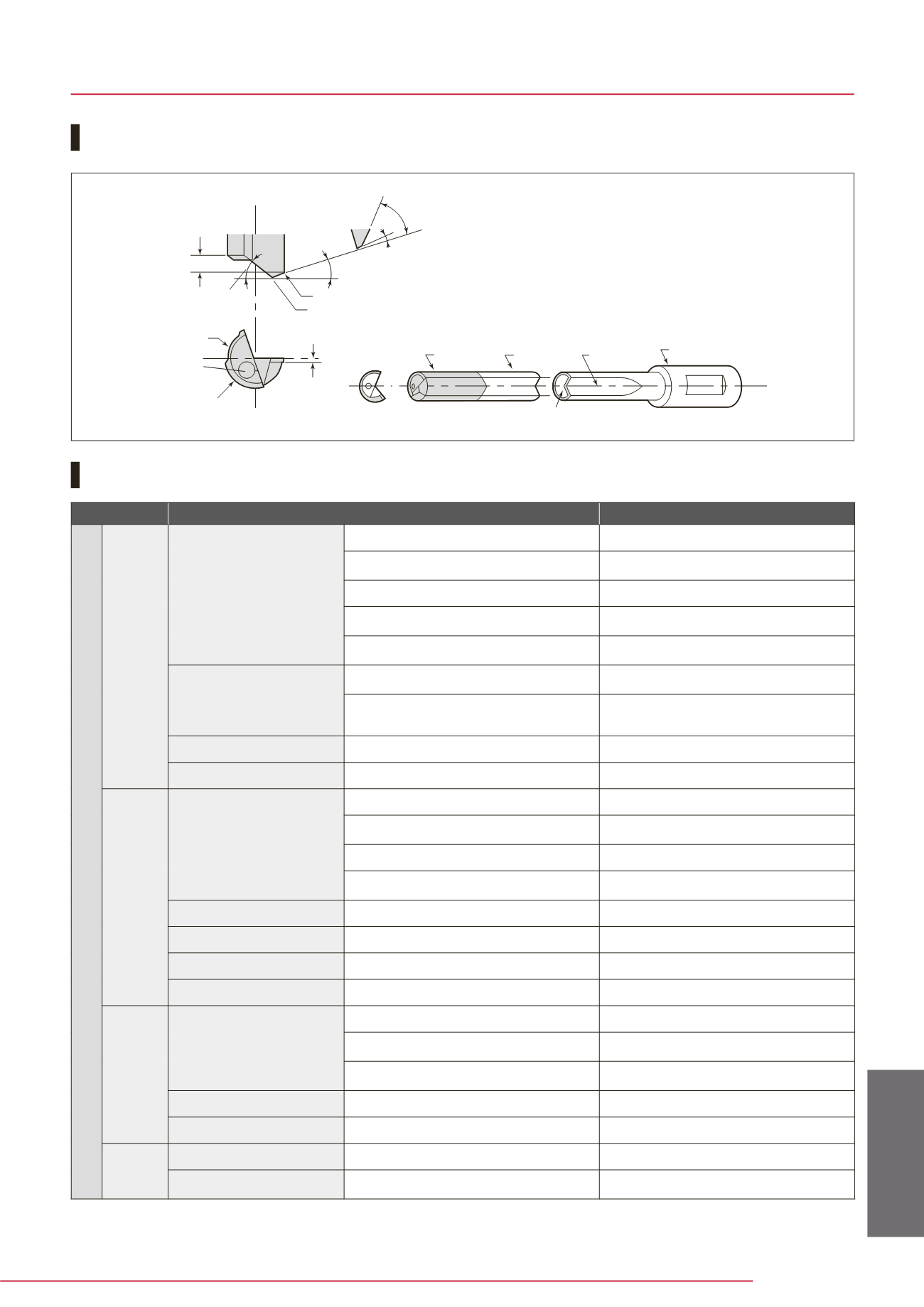
Nomenc l ature for gun dr i l l
Troubl eshoot ing in gun dr i l l ing
Chamfer
Tip
Margin
Apex point
Outer corner
Outer cutting angle
Primary clearance angle 8˚~15˚
Secondary clearance angle
Shank oil hole
Wear surface
(Guide pad)
Oiling hole
Oil clearance
Inner cutting angle
Driver
V-flute
Shank
Dr i l l ing Tool s


