D208
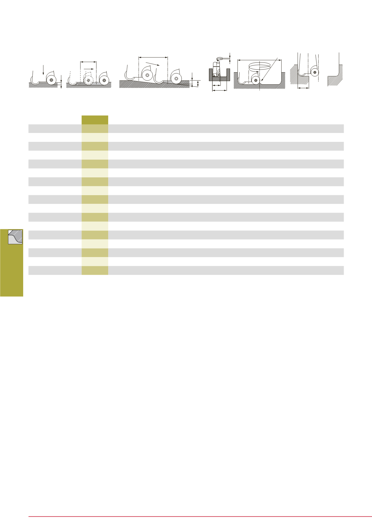
Profile Milling
Ramping
Plunging + traverse feed milling
(Unit: mm)
Unit: mm
Max.
plunging
depth
Max.
ramping
angle
Min. traverse length
to flatten the
bottom surface
Min.
machining
diameter
Max.
machining
diameter
Pitch øDc-ra
Designation
øD
1
ap
θ°
L
øD
øD
P
ae
TRD12050R...
50
4
6
ø
D
1
- 11
88
98
< 6
44
TRD12052R-E
52
4
5.5
ø
D
1
- 11
92
102
< 6
46
TRD12063R...
63
4
4
ø
D
1
- 11
114
124
< 6
57
TRD12066R...
66
4
4
ø
D
1
- 11
120
130
< 6
60
TRD12080R...
80
4
2.5
ø
D
1
- 11
148
158
< 6
74
TRD12100R...
100
4
1.5
ø
D
1
- 11
188
198
< 6
94
TRD16063R...
63
5.5
6
ø
D
1
- 15
110
124
< 8
55
TRD16066R...
66
5.5
6
ø
D
1
- 15
120
130
< 8
58
TRD16080R...
80
5.5
4
ø
D
1
- 15
144
158
< 8
72
TRD16100R...
100
5.5
3
ø
D
1
- 15
184
198
< 8
92
ERD12032RS/L
32
4
16
ø
D
1
- 11
52
62
< 6
26
ERD12040RS/L
40
4
8
ø
D
1
- 11
68
78
< 6
34
ERD12050RS/L
50
4
6
ø
D
1
- 11
88
98
< 6
44
ERD12063RS/L
63
4
4
ø
D
1
- 11
114
124
< 6
57
ERD16040RS/L
40
5.5
20
ø
D
1
- 15
64
78
< 8
32
ERD16050RS/L
50
5.5
10
ø
D
1
- 15
84
98
< 8
42
ERD16063RS/L
63
5.5
6
ø
D
1
- 15
110
124
< 8
55
ø
D
1
: Tool diameter
ø
D
: Drilling diameter
P : Z-axis feed per one round of tool pass (Pitch of helical cycle)
Notes: • In plunging, the maximum plunging depth is limited as shown in the above table.
• In plunging, set the Z-axis feed in a range of 0.05 to 0.1 mm/t.
• When plunging, use peck-feed every 1 mm (or smaller than 1 mm) to break chips.
• tanθ = depth of cut: ap / length of tool pass: L
• In ramping, the ramping angle should be set within the maximum ramping angle.
•
In helical feed hole machining, the machinable hole diameters are limited by the tool diameter as shown in the above tables.
•
When machining between the minimum and maximum machining diameters, a projection remains in the center of the bottom surface of the hole
as shown in the Figure at right. Remove it by traverse feed milling.
ae
øD
1
øD
P
Helical feed drilling
Plunging
Traverse feed milling
ap
Feed
Feed
L
Feed
L
ap
θ
°
øD


