D014
High-Feed Milling
STANDARD CUTTING CONDITIONS TXN06 / EXN06
0.5
1.0
1.5
2.0
1.5
1.0
0.5
0
1.5
2
6
2
1
-
3
0.77
-
4
0.54 0.26
V
c = 80 ~ 200 m/min
V
c = 100 ~ 300 m/min
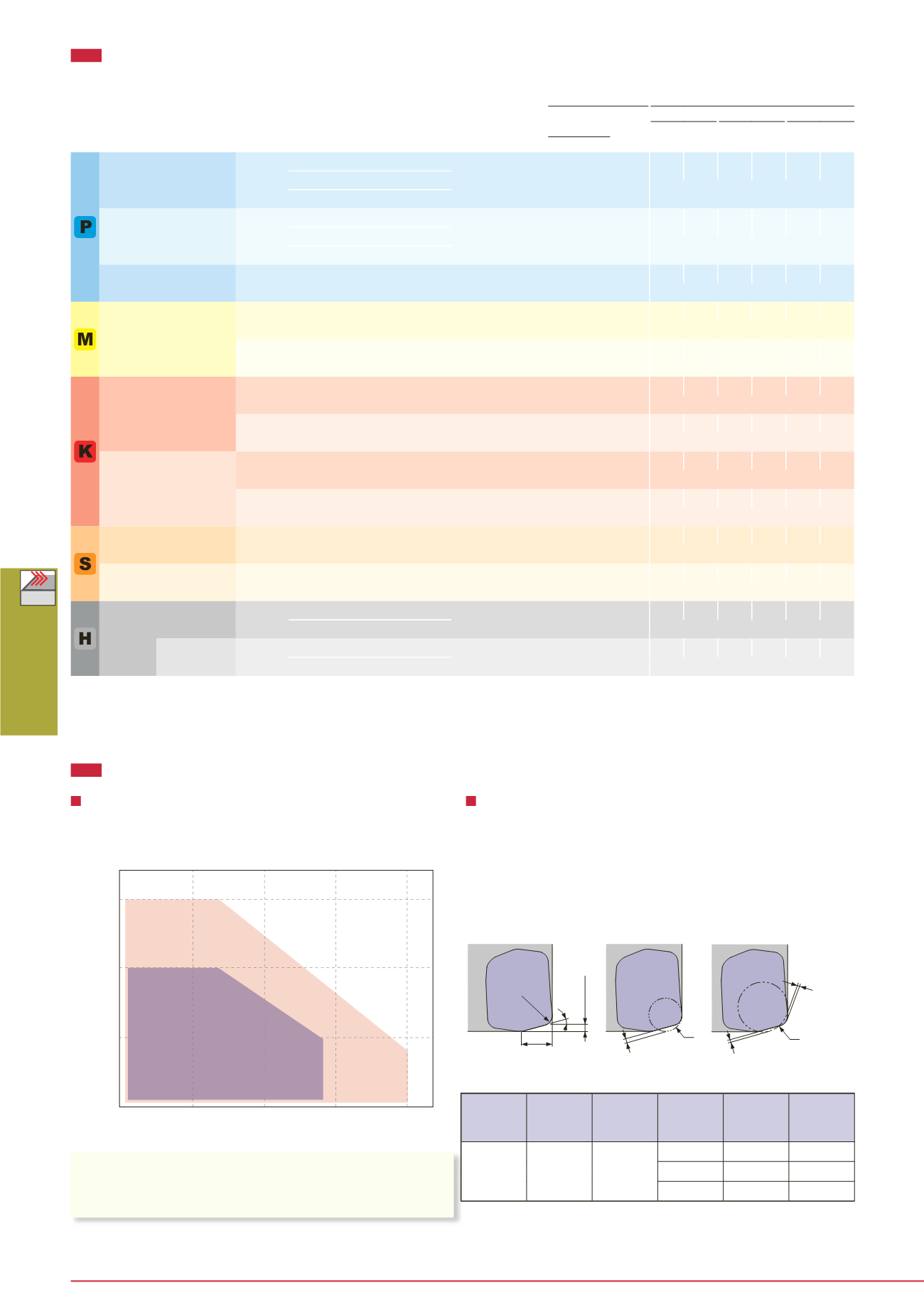
Tool geometry on program
When programming for CAM, the tool should be considered
as a radius cutters. Usually, the corner radius should be
set as R = 3 mm. If a larger radius is used, overcutting will
occur. The following table shows the amount left as uncut (t
1
)
and overcut (t
2
).
The usage of a standard & long shank
When using a long shank, please lower the cutting
conditions (
V
c,
f
z,
a
p) to 70% of the maximum conditions
for the standard shank.
Tool dia.: ø
D
c = ø32 ~ 40 mm
Workpiece material: C55 (200HB)
L/D ratio of overhang
Standard shank: L/D ≤ 3
Long shank: L/D = 4
Standard shank
Long shank
Depth of cut:
a
p (mm)
Feed per tooth:
f
z (mm/t)
Corner
radius
Amount left
as uncut
Corner R
when
program-
ming
Each value in table is calculated theoretically at the maximum condition.
Amount left
as overcut
When chips stay in the cutting zone during slotting or pocketing, use air
blast to remove chips from the work area.
Tool overhang length must be as short as possible to avoid chatter. When
the tool overhang length is long, decrease the number of revolutions and
feed.
w
r
ε
15°
R
R
t
2
t
1
t
1
max.
a
p
Amount left
as overcut
Max. depth of cut
Corner R when
programming
Amount left
as uncut
Max. depth
of cut
max.
a
p
(mm)
r
ε
W
(mm)
t
1
t
2
CAUTIONARY POINTS IN USE
ISO Workpiece material
Hardness
Priority
Grade
Chip-
breaker
Cutting
speed
Feed per tooth:
fz (mm/t)
Vc
(m/min)
Tool dia.:
øDc (mm) Plung-
ing
ø32, z = 2 ø35, z = 2 ø40, z = 3
n Vf
n Vf
n Vf
ø32 ~ ø200
Carbon steel
C45, C55, etc.
~ 300HB
First choice
AH725
MJ 100 - 300 0.5 - 1.5 0.15
1,990 3,980 1,820 3,640 1,590 4,770
For wear resistance AH120
Vc = 200 m/min, fz = 1 mm/t
For impact resistance AH3035
Alloy steel
42CrMo4, 17Cr3, etc.
~ 300HB
First choice
AH725
MJ 100 - 200 0.5 - 1.5 0.15
1,490 2,980 1,360 2,720 1,190 3,570
For wear resistance AH120
Vc = 150 m/min, fz = 1 mm/t
For impact resistance AH3035
Prehardened steel
NAK80, PX5, etc.
30 ~
40HRC
-
AH3035 ML 100 - 200 0.5 - 1 0.15
1,490 2,380 1,360 2,180 1,190 2,860
Vc = 150 m/min, fz = 0.8 mm/t
Stainless steel
X5CrNi18-10,
X5CrNiMo17-12-2, etc.
~ 200HB First choice
AH130 ML 100 - 150 0.3 - 0.7 0.1
1,190 1,190 1,090 1,090 950 1,430
Vc = 120 m/min, fz = 0.5 mm/t
~ 200HB For impact resistance AH130 MJ 100 - 150 0.3 - 0.8 0.1
1,190 1,430 1,090 1,310 950 1,710
Vc = 120 m/min, fz = 0.6 mm/t
Grey cast iron
GG25, GGG30, etc.
150 ~
250HB
First choice
AH120 MJ 100 - 300 0.5 - 1.5 0.15
1,990 3,980 1,820 3,640 1,590 4,770
Vc = 200 m/min, fz = 1 mm/t
150 ~
250HB
For low cutting force AH120 ML 100 - 300 0.5 - 1 0.15
1,990 3,180 1,820 2,910 1,590 3,820
Vc = 200 m/min, fz = 0.8 mm/t
Ductile cast iron
GGG40, etc.
150 ~
250HB
First choice
AH120 MJ 80 - 200 0.5 - 1.5 0.15
1,490 2,980 1,360 2,720 1,190 3,570
Vc = 150 m/min, fz = 1 mm/t
150 ~
250HB
For low cutting force AH120 ML 80 - 200 0.5 - 1 0.15
1,490 2,380 1,360 2,180 1,190 2,860
Vc = 150 m/min, fz = 0.8 mm/t
Titanium alloys
Ti-6AI-4V, etc.
~ 40HRC
-
AH725 ML 30 - 60 0.3 - 0.7 0.08
400 400 360 360 320 480
Vc = 40 m/min, fz = 0.5 mm/t
Heat-resistant alloys
Inconel, Hastelloy, etc.
~ 40HRC
-
AH725 MJ 20 - 50 0.1 - 0.3 0.05
300 120 270 110 240 140
Vc = 30 m/min, fz = 0.2 mm/t
Hardened
steel
X40CrMoV5-1,
etc.
40 ~
50HRC
First choice
AH3035
MJ 80 - 130 0.1 - 0.3 0.05
990 400 910 360 800 480
For wear resistance AH725
Vc = 100 m/min, fz = 0.2 mm/t
X153CrMoV12,
etc.
50 ~
60HRC
First choice
AH725
MJ 50 - 70 0.03 - 0.07 0.03
600 60 550 60 480 70
For impact resistance AH3035
Vc = 60 m/min, fz = 0.05 mm/t


