D005
Tungaloy
High-Feed Milling
INSERT
P Steel
★
M Stainless
★
K Cast iron
★
N Non-ferrous
★
S Superalloys
H Hard materials
Designation
Max.
a
p
Coating
A B T
AH730
DS1200
XXGT06H205EC-MJ
0.6
l
6.2 4.9 2.5
XXGT07X305EC-MJ
0.6
l
7 5.9 3
XXGT09X408EC-MJ
0.8
l
8.9 7.9 4
XXGT06H205FC-AJ
0.6
l
6.2 4.9 2.5
XXGT07X305FC-AJ
0.6
l
7 5.9 3
XXGT09X408FC-AJ
0.8
l
8.9 7.9 4
XXGT06H205EP-MJ
0.6
l
6.2 5.1 2.5
XXGT07X305EP-MJ
0.6
l
7 6.3 3
XXGT09X408EP-MJ
0.8
l
8.9 8 4
XXGT06H205FP-AJ
0.6
l
6.2 5.1 2.5
XXGT07X305FP-AJ
0.6
l
7 6.3 3
XXGT09X408FP-AJ
0.8
l
8.9 8 4
l
: Line-up
: First choice
: Second choice
STANDARD CUTTING CONDITIONS
Shoulder milling
,
Slotting
Note:
¡
In slotting or pocketing where chips tend to stay in the cutting
zone, use an air blast to remove chips for preventing chip recutting.
¡
When chips tend to weld excessively on the cutting edge such as
in machining aluminium alloys, use a water soluble cutting fluid.
¡
In the case of cutting a casting skin or a heavily interrupted
work surface, decrease the feed per tooth and the maximum
depth of cut to 1/2 to 2/3 times the values shown in the table.
¡
Tool overhang length must be as short as possible to avoid
chatter. When the tool overhang length is long, decrease the
number of revolutions and feed.
¡
Cutting conditions are generally limited by the rigidity and power
of the machine and the rigidity of the workpiece. When setting
the conditions, start from half of the values of the standard
cutting conditions and then increase the value gradually whilst
making sure that the machine is running normally.
Side cutting
a
p: Axial depth of cut
Slotting
Plunging
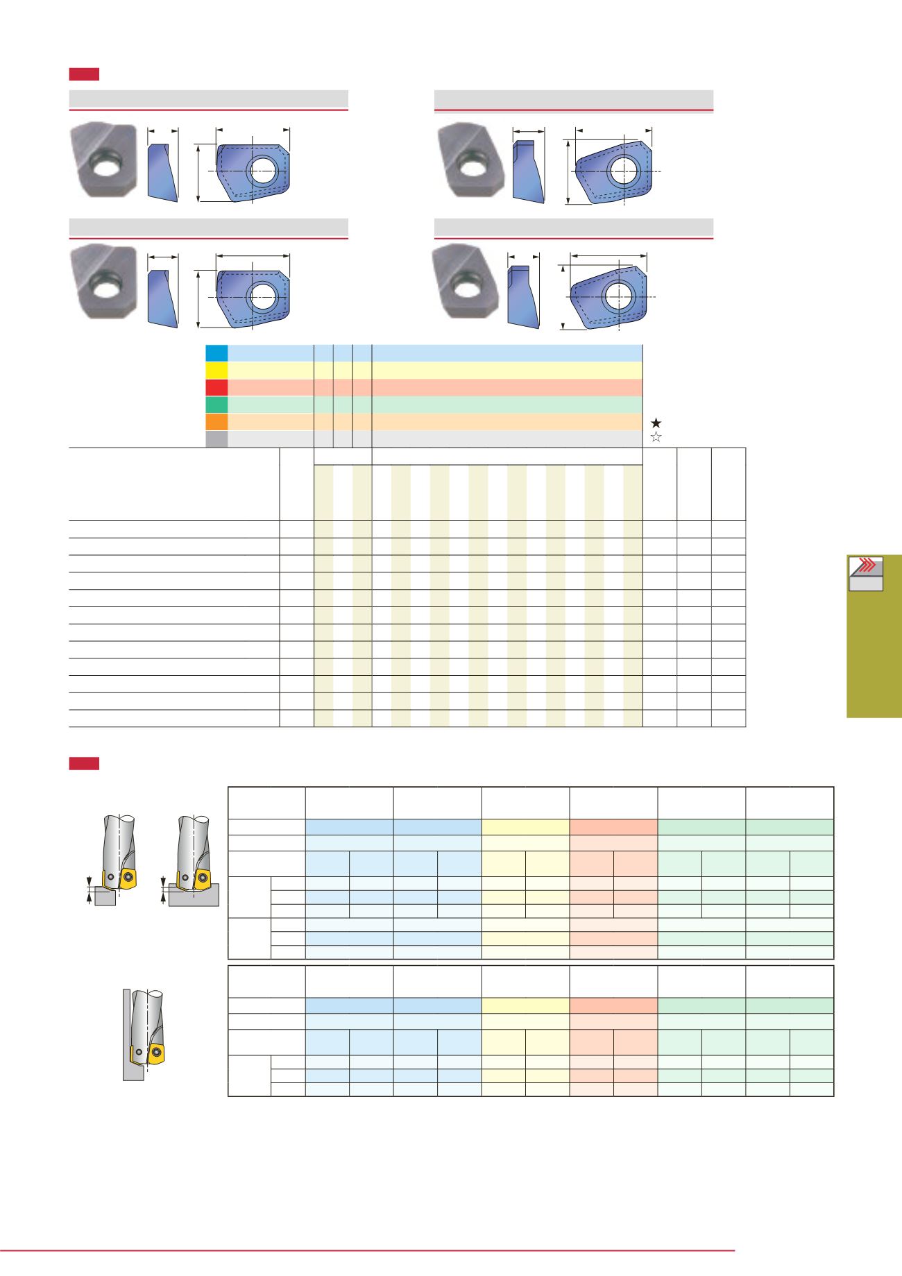
XXGT EP-MJ
(Peripheral cutting edge)
A
B
T
XXGT FP-AJ
(Peripheral cutting edge)
A
B
T
XXGT EC-MJ
(Center cutting edge)
A
B
T
XXGT FC-AJ
(Center cutting edge)
A
B
T
ap
ap
ap
Workpiece
material
Carbon steels and
alloy steels
Alloy steels and
prehardened steelst Stainless steels Cast irons
Aluminium alloys
(Si
<
13%)
Aluminium alloys
(Si
≥
13%)
Hardness
< 30HRC
30 ~ 40HRC
< 250HB
-
-
-
Cutting speed
V
c = 100 ~ 300 m/min
V
c = 100 ~ 250 m/min
V
c = 100 ~ 300 m/min
V
c = 100 ~ 300 m/min
V
c = 100 ~ 500 m/min
V
c = 100 ~ 300 m/min
Conditions
No. of rev.
n
min
-1
Feed speed
V
f
mm/min
No. of rev.
n
min
-1
Feed speed
V
f
mm/min
No. of rev.
n
min
-1
Feed speed
V
f
mm/min
No. of rev.
n
min
-1
Feed speed
V
f
mm/min
No. of rev.
n
min
-1
Feed speed
V
f
mm/min
No. of rev.
n
min
-1
Feed speed
V
f
mm/min
Tool dia.
(mm)
ø10
4770 1430 3820 760 4770 1430 6360 2540 9550 5730 6360 3180
ø12
3980 1190 3180 630 3980 1190 5300 2120 7950 4770 5300 2650
ø16
2980 890 2380 470 2980 890 3970 1580 5960 3570 3970 1980
Depth of
cut
ø10
a
p < 0.6
a
p < 0.5
a
p < 0.6
a
p < 0.6
a
p < 0.6
a
p < 0.6
ø12
a
p < 0.6
a
p < 0.5
a
p < 0.6
a
p < 0.6
a
p < 0.6
a
p < 0.6
ø16
a
p < 0.8
a
p < 0.6
a
p < 0.8
a
p < 0.8
a
p < 0.8
a
p < 0.8
Workpiece
material
Carbon steels and
alloy steels
Alloy steels and
prehardened steelst Stainless steels Cast irons
Aluminium alloys
(Si
<
13%)
Aluminium alloys
(Si
≥
13%)
Hardness
< 30HRC
30 ~ 40HRC
< 250HB
-
-
-
Cutting speed
V
c = 100 ~ 300 m/min
V
c = 100 ~ 250 m/min
V
c = 100 ~ 300 m/min
V
c = 100 ~ 300 m/min
V
c = 100 ~ 500 m/min
V
c = 100 ~ 300 m/min
Conditions
No. of rev.
n
min
-1
Feed speed
V
f
mm/min
No. of rev.
n
min
-1
Feed speed
V
f
mm/min
No. of rev.
n
min
-1
Feed speed
V
f
mm/min
No. of rev.
n
min
-1
Feed speed
V
f
mm/min
No. of rev.
n
min
-1
Feed speed
V
f
mm/min
No. of rev.
n
min
-1
Feed speed
V
f
mm/min
Tool dia.
(mm)
ø10
4770 240 3820 150 4770 240 6360 440 9550 760 6360 440
ø12
3980 200 3180 130 3980 200 5300 370 7950 640 5300 370
ø16
2980 150 2380 95 2980 150 3970 280 5960 480 3970 280


