E033
Tungaloy
2-eective Drill
6
5
4
3
2
1
0
3.5
3
2.5
2
1.5
1
0.5
0
20
16
12
8
4
3 5
10
15
20
2 4 6 8 10 12 14 16 18
0.30
0.25
0.20
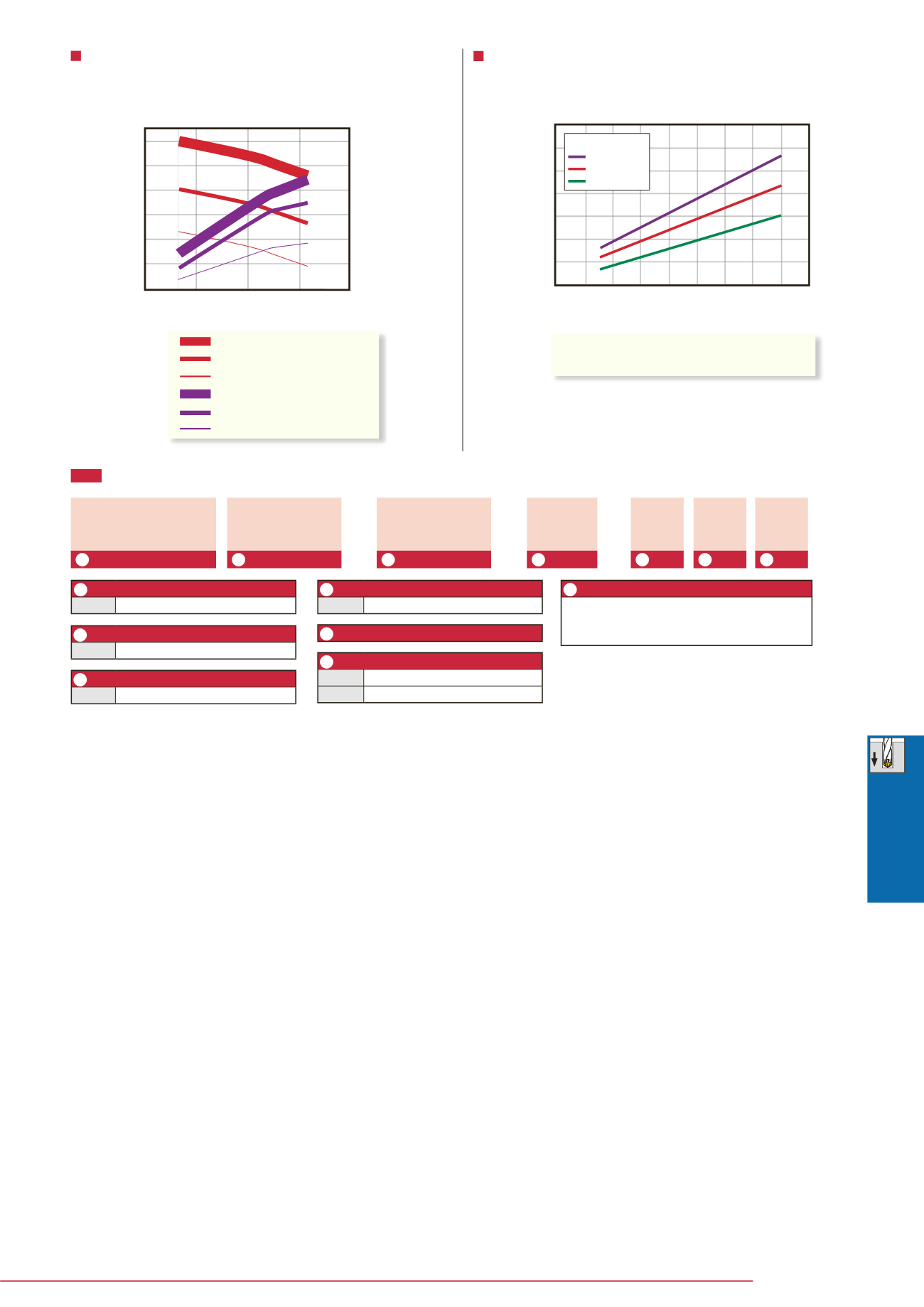
Recommended coolant pressure and volume for
internal coolant supply:
Reference for required spindle power:
The following graph is a reference guide for pressure and
volume. Values should be adjusted according to work
material and actual chip evacuation.
The required spindle power may vary depending on the type
of work material or hardness. A spindle with sufficient power
should be used when referring to the below graph.
Drill diameter øDc (mm)
Drill diameter øDc (mm)
Coolant pressure
p (MPa)
Net power consumption
(kW)
Coolant volume
V (l/min)
:
I
deal pressure
:
Enough pressure
:
Minimum pressure
:
Ideal volume
:
Enough volume
:
Minimum volume
Work material
Cutting speed
: Alloy steel (SNCM439)
: Vc = 100 m/min
Feed
f
(mm/rev)
035
35
088
ø8.8
DSW
E
I
10
ø10
Des ignat ion system
Series
Eective flute length
r
e
(mm)
Drill dia. ø
D
c (mm)
Series name of solid drill
Shank diameter
ø
D
s
(mm)
Coolant Supply
DIN 6535 - Form HA
External (without coolant hole)
Internal (with coolant hole)
Drilling depth
Approximate value of L/D ratio.
Caution: Code may be di¯erent from the actual
length. This is dependent upon the tool diameter.
Caution: “Eective flute length” shows the maxi-
mum flute length for eective chip evacuation.
The actual drilling depth may be shorter than de-
scribed depending on the work material or cutting
conditions.
DSW 088 035 10 D E 3
-
- -
1
2
3
4
5
6
7
1
3
2
4
6
5
7


