E036
2-e ective Drill
Regr i nd i ng Procedures
θ
1
°
θ
2
°
θ
3
°
C
A
B
–20°
–6° ~ –12° –23° ~ –27°
β
1
β
2
β
3
147° ~ 153°
30° ~ 42°
95° ~ 110°
θ
1
θ
2
θ
3
DSW
DSW
θ
1
°
θ
2
°
θ
3
°
C
A
B
A A
0.02 ~ 0.04
0.03 ~ 0.05
θ
- 20º
- 20º
- 20º
H
0.03 ~ 0.05
0.05 ~ 0.08
0.08 ~ 0.1
ø6 ~ ø10 mm
ø10 ~ ø16 mm
~ ø6 mm
Table 1
Table 2
0
β
1
β
2
β
3
Fig. 2
•
R
Honing
•
Angle
honing
øDc
≤
ø6
ø6
<
øDc
≤
ø16
R
Check the cutting edge for damage and wear. If any large fracture is found, remove with a silicon carbide wheel.
Before regrinding
Regrinding method
[Applied to DSW]
R
Honing
R (mm)
Dimensions (mm)
After regrinding, check the following before use.
• The di¯erence of the lip height is kept within 0.02 mm.
• Any damaged portion on the cutting edges is not left.
• Cutting edges are properly honed.
• Any grinding burr is not left.
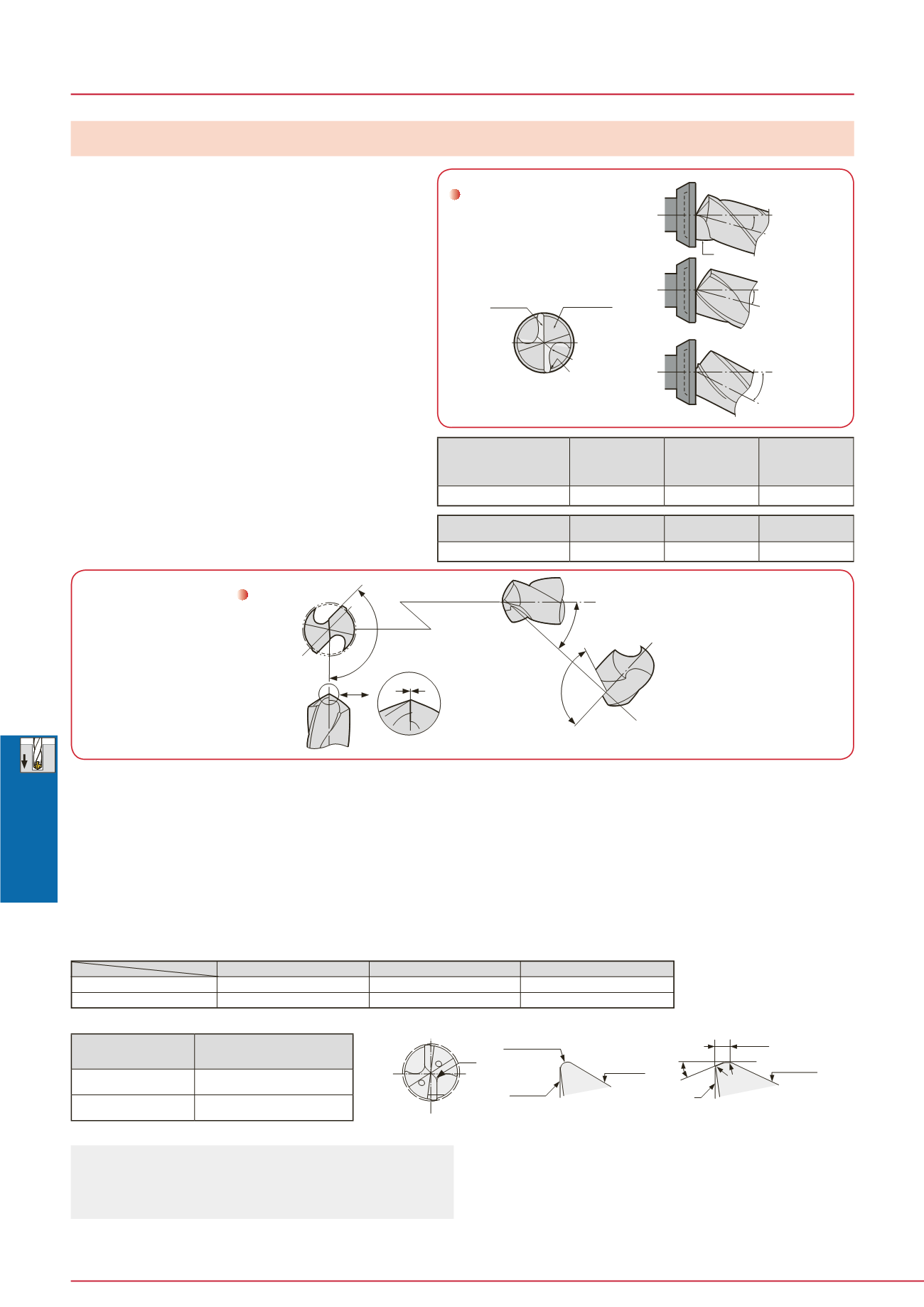
(1) Grinding the flank
Use a 280 to 400 grit diamond cup type wheel of 100 ~ 200
mm in diameter.
1) Grind the relief surface so that primary relief angle (
θ
) of 2°
can be formed as shown in Fig.1. After grinding the other
side likewise, do sparkout grinding so that the di¯erence of
the lip height will be kept within
0.02 mm.
2) In the cases of DSW types: After grinding the primary relief
angle (
θ)
2°, without rotating the drill, grind the secondary
relief surface so that the relief angle (
θ
) of 3° can be formed.
In the same way as 2), take care to bring the ridge line
formed between the primary and secondary relief surfaces
to the drill center. (Values (
θ
) of 1° ~ 3° are shown in Table 1)
(2) Thinning
• Use a 280 ~ 400 grit diamond straight-type wheel of 100 ~ 200
mm in diameter.
• Conduct thinning in the same manner as cross thinning (X-type).
• Values of
β
1 to
β
3 written in the figures are given in the Table 2.
Fig. 1 Grinding relief angle
Point angle
Primary relief
angle
Secondary
relief angle
Viewed from C.
Viewed from C.
Primary
relief
Secondary
relief
Using points A and B as
reference, obtain level.
(Point angle)
(Primary relief
angle)
(Secondary relief
angle)
• The honing angle
θ
and width H should be varied depending on the
drill type, diameter, and work material. Recommended honing specifications are given in
the Table below.
• Honing procedures (refer to Fig.3)
(1) Round the R portion shown in Fig.3 in large.
(2) Then, roughly hone the cutting edge lines by using an electro-deposited diamond file of
around 170 grit.
(3) Carry out finish honing by using a diamond hand stick of 400 to 600 grit.
• The honing width should be changed depending on the drill diameter. For smaller side of
diameters, the width should be in smaller side of values given in the Table.
(3) Honing
Notes:
• For more details on regrinding, consult the nearest Tungaloy sales o·ce.
R Honing
Rake
face
Rake face
Relief surface
Relief surface
Width H
Angle
θ
R Honing
(A-A section)
Angle Honing
(A-A section)


