E034
2-e ective Drill
STANDARD CUTTING CONDITIONS
ISO
Workpiece material
Brinell
hardness (HB)
Cutting speed:
Vc
(m/min)
Feed: f (mm/rev)
ø3 ~ ø6 ø6 ~ ø10 ø10 ~ ø16 ø3 ~ ø6 ø6 ~ ø10 ø10 ~ ø16
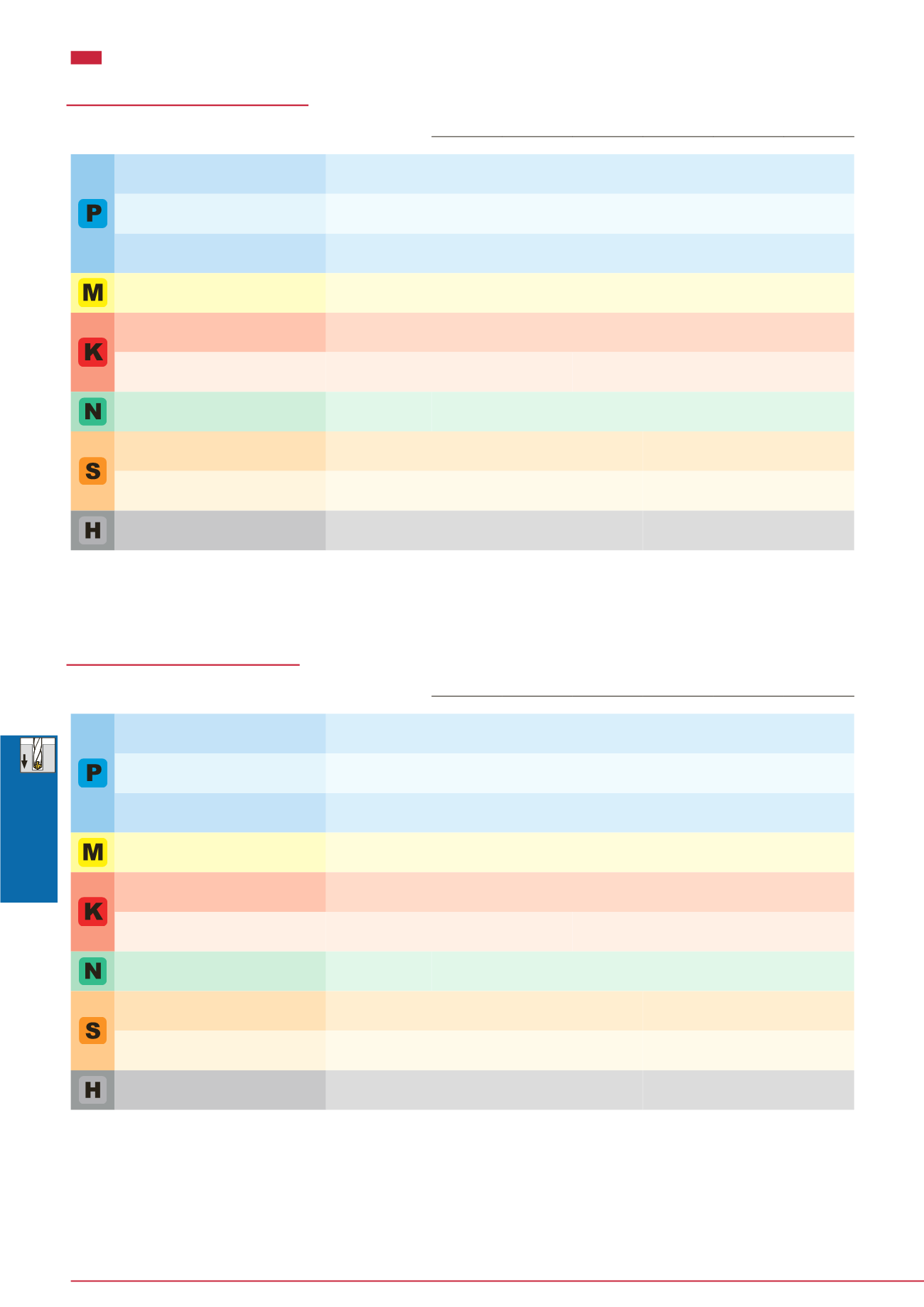
Low carbon steels (C < 0.3)
C15E4, E275A, E355D, etc.
~ 180
40 - 100 60 - 120 60 - 130 0.15 - 0.3 0.15 - 0.35 0.2 - 0.5
Carbon steels (C > 0.3)
C45, C55, etc.
180 ~ 300
40 - 90
50 - 120 60 - 130 0.15 - 0.3 0.15 - 0.35 0.2 - 0.4
High alloy steels
42CrMo4, etc.
250 ~ 350
40 - 80
50 - 100 50 - 100 0.1 - 0.2 0.15 - 0.3 0.15 - 0.35
Stainless steels
X5CrNi18-9, etc.
~ 200
20 - 40
30 - 50
30 - 60 0.05 - 0.2 0.1 - 0.25 0.1 - 0.3
Grey cast irons
250, etc.
~ 200
40 - 90
50 - 95
50 - 100 0.15 - 0.3 0.2 - 0.4 0.2 - 0.5
Ductile cast irons
450-10S, etc.
~ 300
30 - 80
40 - 90
45 - 90
0.1 - 0.3 0.2 - 0.4 0.2 - 0.4
Aluminium alloys
AlSi11Cu3, etc.
-
40 - 90
50 - 100 50 - 100 0.15 - 0.3 0.2 - 0.4 0.2 - 0.5
Titanium alloys
Ti-6Al-4V, etc.
-
20 - 40
20 - 40
20 - 40
0.1 - 0.2 0.15 - 0.25 0.15 - 0.4
Heat-resistant alloys, Inconel
Inconel 718, etc.
250 ~
10 - 30
10 - 30
10 - 30 0.03 - 0.07 0.05 - 0.1 0.07 - 0.12
High hardened steels
X153CrMoV12, etc.
~ 40HRC
20 - 40
20 - 40
20 - 40 0.05 - 0.15 0.05 - 0.15 0.05 - 0.2
DSW-DE (Externa l suppl y )
´ The cutting parameters shown in the table are merely a starting guideline
for general machining. Values should be varied depending on the power or
rigidity of the machine to be used. Optimum conditions should be selected
depending on the actual chip control or damage on edges.
´ When using the smaller diameter tools in each range, set the feed “f” to the
lower recommended values.
´ The coolant supply is critical for the provision of stable machining condi-
tions and enhanced tool life. A large coolant volume should be supplied,
especially when drilling di·cult-to-cut materials.
´ When drilling stainless steel with low machinability such as austenitic stain-
less steel with a depth deeper than L/D = 3, a pecking cycle or internal
coolant supply is recommended.
ISO
Workpiece material
Brinell
hardness (HB)
Cutting speed:
Vc
(m/min)
Feed: f (mm/rev)
ø3 ~ ø6 ø6 ~ ø10 ø10 ~ ø16 ø3 ~ ø6 ø6 ~ ø10 ø10 ~ ø16
Low carbon steels (C < 0.3)
C15E4, E275A, E355D, etc.
~ 180
70 - 140 80 - 160 90 - 190 0.15 - 0.3 0.15 - 0.35 0.2 - 0.5
Carbon steels (C > 0.3)
C45, C55, etc.
180 ~ 300
50 - 130 70 - 160
80 - 170 0.15 - 0.3 0.15 - 0.35 0.2 - 0.4
High alloy steels
42CrMo4, etc.
250 ~ 350
40 - 100 60 - 140 60 - 160 0.1 - 0.2 0.15 - 0.3 0.15 - 0.35
Stainless steels
X5CrNi18-9, etc.
~ 200
25 - 75
50 - 100 50 - 120 0.05 - 0.2 0.1 - 0.25 0.1 - 0.3
Grey cast irons
250, etc.
~ 200
80 - 140 100 - 160 100 - 180 0.15 - 0.3 0.2 - 0.4 0.2 - 0.5
Ductile cast irons
450-10S, etc.
~ 300
70 - 140 80 - 150 80 - 170
0.1 - 0.3 0.2 - 0.4 0.2 - 0.45
Aluminium alloys
AlSi11Cu3, etc.
-
60 - 200 60 - 200 60 - 200 0.15 - 0.3 0.2 - 0.4 0.2 - 0.5
Titanium alloys
Ti-6Al-4V, etc.
-
20 - 60
30 - 80
30 - 80
0.1 - 0.2 0.1 - 0.25 0.15 - 0.4
Heat-resistant alloys, Inconel
Inconel 718, etc.
250 ~
10 - 30
10 - 40
10 - 40 0.03 - 0.07 0.05 - 0.1 0.07 - 0.15
High hardened steels
X153CrMoV12, etc.
~ 40HRC
20 - 50
30 - 60
30 - 60 0.05 - 0.15 0.05 - 0.15 0.05 - 0.2
DSW-DI (Interna l suppl y)
´ The cutting parameters shown in the table are merely a starting guideline
for general machining. Values should be varied depending on the power or
rigidity of the machine to be used. Optimum conditions should be selected
depending on the actual chip control or damage on edges.
´ When using the smaller diameter tools in each range, set the feed “f” to the
lower recommended values.
´ Oil holes that become blocked may cause drill breakages. A filter to prevent
the circulation of chips must be used on the coolant supply system.


