D025
Tungaloy
High-Feed Milling
ISO
- 300 HB
AH3135
MJ
100 - 300
0.5 - 2
- 300 HB
AH120
MJ
100 - 300
0.5 - 2
- 300 HB
AH3135
MJ
100 - 200
0.5 - 2
- 300 HB
AH120
MJ
100 - 200
0.5 - 2
30 - 40 HRC
AH3135
MJ
100 - 200
0.5 - 1.5
30 - 40 HRC
AH120
MJ
100 - 200
0.5 - 1.5
- 200 HB
AH3135
MJ
100 - 150
0.3 - 1
150 -250 HB
AH120
MJ
100 - 300
0.5 - 2
150 -250 HB
AH120
MJ
80 - 200
0.5 - 2
- 40 HRC
AH3135
MJ
30 - 60
0.3 - 0.7
- 40 HRC
AH120
MJ
20 - 50
0.1 - 0.3
40 - 50 HRC
AH3135
MJ
80 - 130
0.1 - 0.3
50 - 60 HRC
AH120
MJ
50 - 70
0.03 - 0.07
STANDARD CUTTING CONDITIONS
R
t
2
t
1
Max. ap
w
14º
r
ε
R
t
2
t
1
Max. ap
w
14º
r
ε
A
a
p
a
e
øD1, 2
W
θ
°
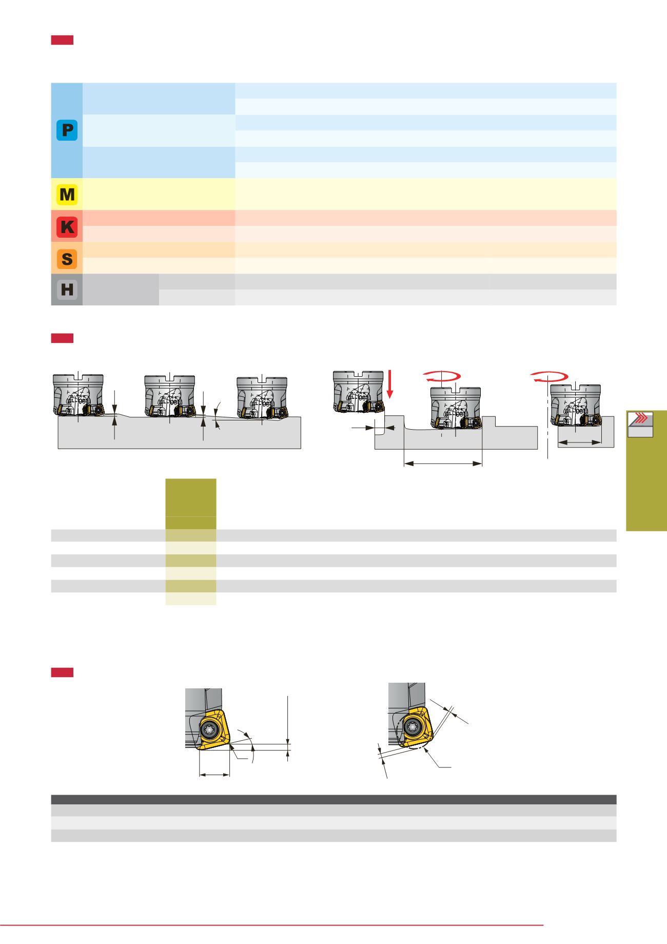
APPLICATION RANGE
TOOL GEOMETRY ON PROGRAM
- When programming for CAM, the tool should be considered as a radius cutter. Usually, the corner radius should be set in R = 4.5 mm.
If a larger radius is used, overcutting may occur. The above table shows the uncut (t1) and overcut (t2) amounts for the programmed corner radius.
Max. ap (mm)
Actual corner radius rε (mm)
W (mm)
Programmed corner radius R (mm) Uncut amount t1 (mm) Overcut amount t2 (mm)
2.5
2
12.7
4
1.99
-
2.5
2
12.7
4.5
1.88
-
2.5
2
12.7
5
1.78
0.01
Shoulder
milling
Small depth
plunging
Plunging
Ramping
Drilling
(Helical feed)
Enlarging hole
Chip-
breaker
Low carbon steel
C15E4, E275A, etc.
First choice
Second choice
First choice
Second choice
First choice
Second choice
First choice
First choice
First choice
First choice
First choice
First choice
First choice
Carbon steel and alloy steel
C55, 42CrMo4, etc.
Prehardened steel
NAK80, PX5, etc.
Stainless steel
X5CrNi18-9, X5CrNiMo17-12-3, etc.
Grey cast iron 250,300, etc.
Ductile cast iron 600-3, etc.
Titanium alloys Ti-6AI-4V, etc.
Superalloys Inconel718, etc.
Hardened steel
X40CrMoV5-1, etc.
X153CrMoV12, etc.
Cutting speed
Vc (m/min)
Feed per tooth
fz (mm/t)
Workpiece material
Grade
Hardness
Priority
Max. depth
of cut
Max.
plunging
depth
Max.
ramping
angle
Max. cutting
width in
plunging
Min.
machining
dia.
Max.
machining
dia.
Max. cutting
width in
enlarging
Designation
øD
c
a
p
A
θº
W
øD
1
øD
2
a
e
TXSW15M050B...
50
2.5
0.7
4.8
15
70
95
36
TXSW15M063B...
63
2.5
0.7
2.9
15
96
121
49
TXSW15M080B...
80
2.5
0.7
2
15
130
155
66
TXSW15M100B...
100
2.5
0.7
1.4
15
170
195
86
TXSW15M125B...
125
2.5
0.7
1
15
220
245
111
TXSW15M160B...
160
2.5
0.7
0.7
15
290
315
146
Tool dia.


