Tungaloy
B407
ød
R
L
C
2
øD
C
1
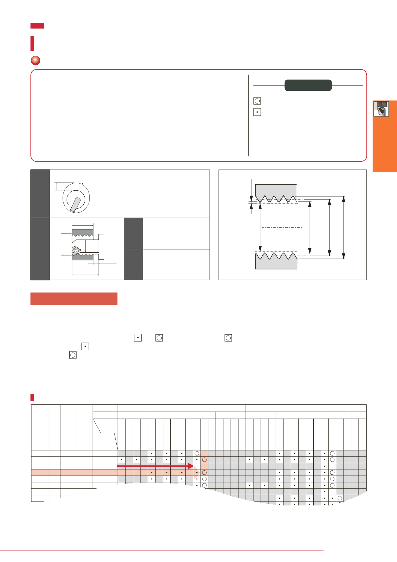
Relation between internal toolholders and machinable threads
In the tables starting from next page, the relationships between toolholders,
inserts, threads to be machined, and shims to be replaced are shown. In these
tables, the criteria are set as follows.
¡
The minimum machining diameter.
¡
The L/D ratio of the toolholder.
¡
The lead angle of the thread.
¡
Cutting conditions
Especially when machining near the minimum machining diameter, the
compensation for the lead angle should be done carefully.
Moreover, in threading, because chips generally can not be broken into small
pieces, the shank size should be selected in consideration of adequate
clearance (C
1
).
Recommended
Usable
x
Needs replacing of the shim.
"2" indicates "Change to the shim
for 2° lead angle".
Unusable
Symbols
Clearance C
1
Overhang ratio L/D
Steel
shank
Carbide
shank
( 1 mm for 6IR insert holders)
Internal diameter
of thread
Stock to be removed with full-profile insert.
External
thread
Internal thread
Minor dia. of
internal thread
Minor dia. of
external thread
Pitch diameter
Prepared
hole diameter
Internal thread
q
Firstly, find the nominal thread diameter. Example: M35 X 1.5
w
The table indicates that the lead angle is 0°48
′
.
e
The Cat. No. of the insert to be used corresponds with IR15ISO.
r
By following the row to the right, and marks are found. The mark indicates the optimum toolholder type. The
toolholders of mark are usable, but less rigid because the shank diameter against the threading diameter is smaller than
those of marked toolholder. In this example, CNR0025R16 and TCNR0020R16DT are the optimum toolholders.
The insert Cat.No. is 16IR15ISO.
t
In the case of M33 X 3 thread, the lead angle is 1°46
′
. By following the row to the right.
x
mark is found. This indicates that
the shim should be replaced to 2° type. For calculation of the lead angle, refer to page
B405
.
How to use the tables
6IR
11IR
16IR
16IR 16IR
22IR
22IR
6IR
11IR
M33 1.5 1.5 32.03 0º51´
IR15ISO
M33 2 2 31.7 1º09´
IR20ISO
M35 1.5 1.5 34.03 0º48´
IR15ISO
M36 1.5 1.5 35.03 0º47´
IR15ISO
M36 2 2 34.7 1º03´
IR20ISO
M38 1.5 1.5 37.03 0º44´
IR15ISO
M39 1.5 1.5 38.03 0º43´
IR15ISO
M33 3 3 31.05 1º46´
IR30ISO
M36 3 3 34.05 1º36´
IR30ISO
™
™
SNR0006H06-3
SNR0008H06-3
SNR0010K11-2
SNR0013L11-2
SNR0016M16-2
SNR0020Q22
SNR0020Q22-2
SNR0006K06SC-3
SNR0008K06SC-3
SNR0010M11SC-2
SNR0012P11SC-2
SNR0016R16SC-2
(TCNR0032T16DT)
CNR0032S16
SNR0006H06-2
SNR0008H06-2
SNR0010K11
SNR0013L11
SNR0006K06SC-2
SNR0008K06SC-2
SNR0010M11SC
SNR0012P11SC
TCNR0025S16DT
CNR0025R16
SNR0016R16SC
SNR0016M16
CNR0025R22
TSNR0020R22
TCNR0025S22DT
CNR0032S22
TSNR0016Q16
TCNR0020R16DT
CNR0020P16
™
™
Steel shank
Carbide shank
Nominal size
Pitch
Effective diameter
Lead angle
Shank material
Insert size
Holder Cat. No.
Insert Cat. No.
“Tsuppari-Ichiban”
(For full size of this table, see page B409.)
Metric fine screw thread (ISO)
C
1
≥
3 mm
L/D
≤
2
➝
L/D
≤
3
➝
Se l ect ion of ST- type Toolholders
Selection of internal threading toolholders
Threading Tool


