Tungaloy
B405
Shim repl acement method of ST- type tool s
β
2
=
β
1
+
β
3
-
β
I
I
θ
β
3
90°-
β
1
β
2
β
α
60°
30°
5.8°
8.8°
55°
27.5°
5.2°
7.9°
30°
15°
2.7°
4.1°
29°
14.5°
2.6°
4°
β
1
θ
β
1
= tan
-1
(tan
θ
•
tan
α
)
P
β
1
°
3
°
1
°
2
°
Standard Compensated
Standard
Compensated
1°
2°
3°
SNR0016M16
SNR0016M16-2
SNR0016M16-3
ø
d
β
P
π
d
2
θ
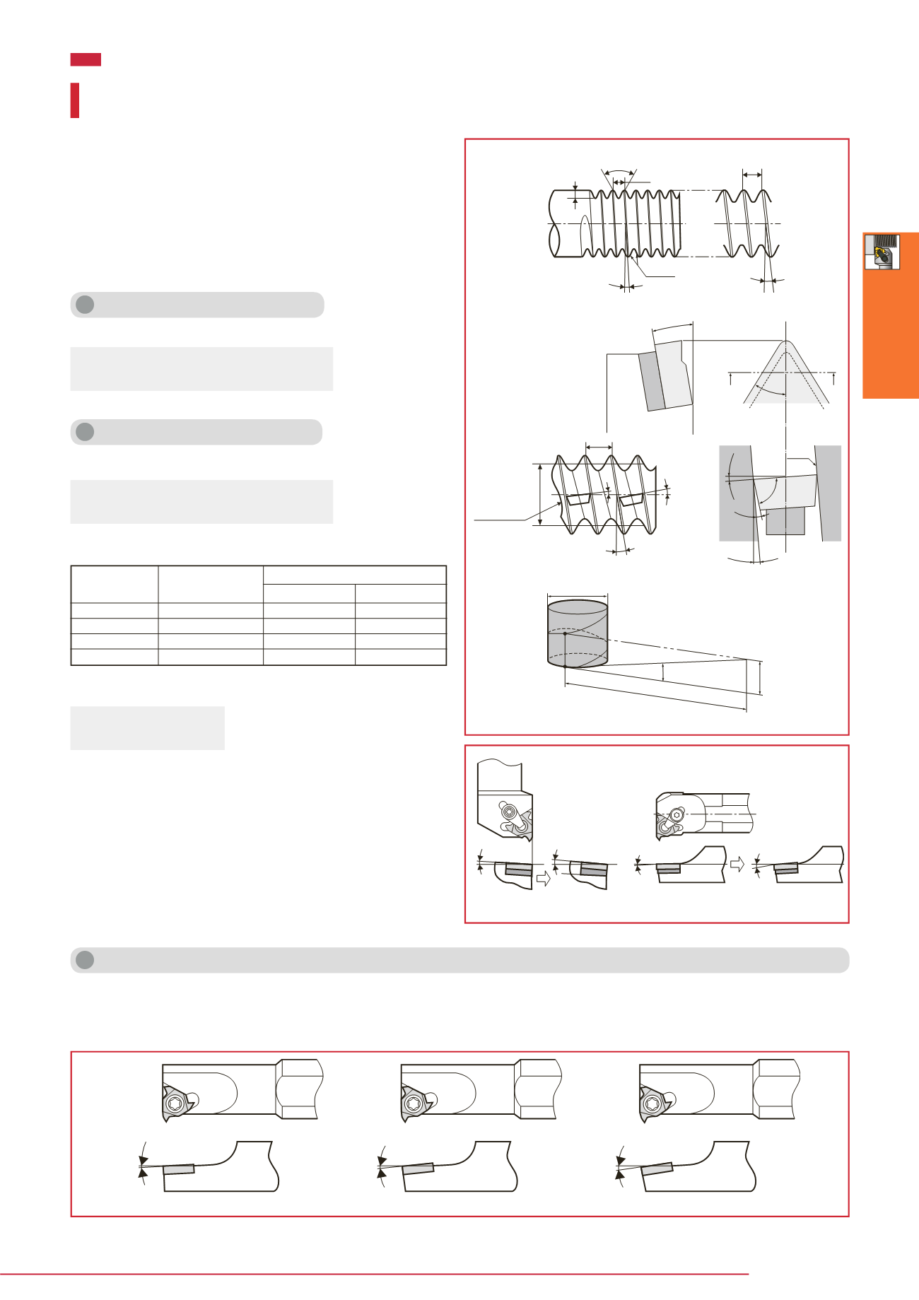
When the pitch is large or the screw diameter is small, the
lead angle becomes large and the effective relief angle on the
advance flank side
β
2
becomes small. In particular, this will
cause shorter life of the insert in the case of trapezoidal screw
with small flank angle. It is ideal without any interference for
the thread cutting insert to have an equal relief angle on both
right and left. Replace the shim so that the rake face of insert
faces the thread groove direction (that is,
β
=
β
3
).
Calculating the lead angle
Calculating the relief angle
The lead angle is calculated as follows:
The relief angle
β
1
is calculated as follows:
The
α
of a standard toolholder is 10˚ for external threading and
15˚ for internal threading.
Accordingly, the effective relief angle is calculated as follows:
β
:
Lead angle
β
2
:
Effective relief angle
β
3
:
Lead angle
compensation value
In other words,
β
1
=
β
2
when the thread lead angle is equal
to the compensation value. Namely, the relief angle of the
tool itself is equal to the effective relief angle. If the wrong
compensation value is used,
β
1
>
β
2
. The effective relief angle
becomes smaller and cause the interference between the
frank side of insert and the thread groove. Therefore, carry
out com-pensation of the lead angle so that the following
range is obtained:
±1˚ when the thread angle is 60˚ and 55˚
±30´ when the thread angle is 30˚ and 29˚
Compensation of lead angle for shim less internal toolholders
When using internal threading toolholders without shim,
the above-mentioned method can not be applied for lead
angle compensation. Therefore, special toolholders for large
lead angles are available as shown below. The final figure of
the designation (-2 or -3) indicates 2° or 3° lead angle to be
used respectively. The toolholders without these figures are
for 1° lead angle.
Thread height
Thread angle
Pitch P (small) = lead
Pitch P (large)
Lead angle
(large)
Insert
Shim
Shim
Toolholder
Thread
groove
Lead angle (small)
Flank
Insert
I–I cross section
(Pitch diameter)
Lead angle
compensation
Pitch
diameter d
Small clearance
(Possibility of
interference)
External threading tool Internal threading tool
Included angle
β
:
Lead angle
R
:
Lead
n
:
No. of threads
P
:
Pitch
d
:
Pitch diameter
Compensation for the lead angle and tool relief angle
β
= tan
-1
(
R
/
π
d
) = tan
-1
(
nP
/
π
d
)
Threading Tool


