B416
Standard Cut t ing Condi t ions and Infeed Methods
0.5 0.75 1 1.25 1.5 1.75 2 2.5 3 3.5 4 4.5 5 ~
48 32 24 20 16 14 12 10
8
7
6 5.5 5 ~
4 ~ 6 4 ~ 7 4 ~ 8 5 ~ 9 6 ~ 10 7 ~ 12 7 ~ 12 8 ~ 14 10 ~ 16 11 ~ 18 11 ~ 18 11 ~ 19 12 ~ 24
Note:
• When using the full-profile insert, set the total infeed amount by
taking the finish stock of 0.1mm into account.
• Set the first infeed to 150 ~ 200% of nose R and do not allow it
to exceed 0.5 mm.
• The infeed amount during the final pass must be a minimum of
0.05 mm. No zero cuts should be made. (Extra small infeed or
zero cutting of work hardened surfaces will reduce tool life.)
• The partial-profile insert or inside diameter insert has small nose
R. Reduce the infeed per pass and increase the no. of passes.
• Regarding standard infeed per passes and no. of passes, please
refer to our catalogue.
Determine the infeed per pass and number of threads
whilst referring to the table and description below.
Threading guidelines
Pitch
TPI
No. of passes
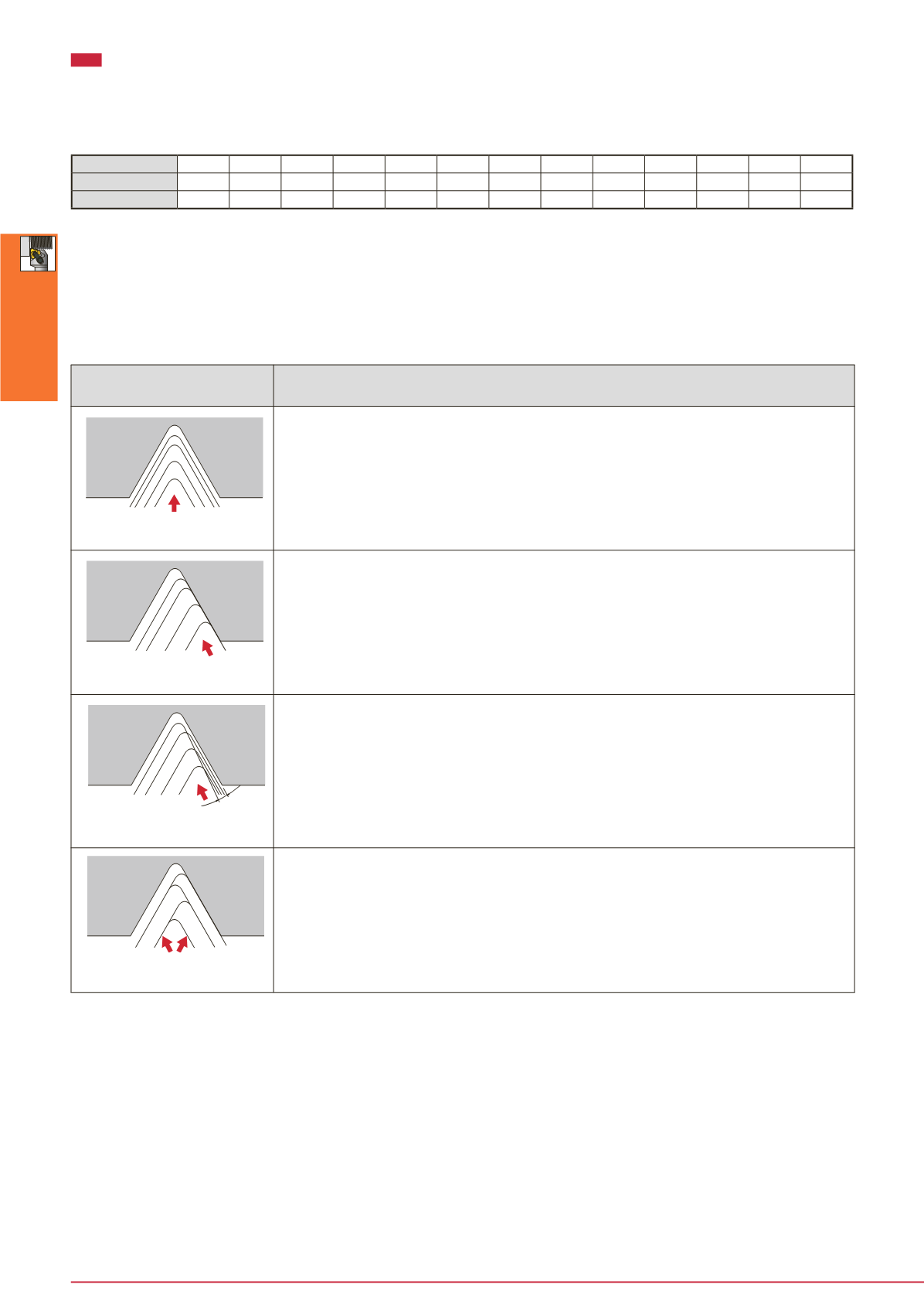
Infeed methods for threading tools
Infeed method
Features
Straight infeed (radial infeed)
Single edge infeed
(flank infeed)
Modified single-edge infeed
(flank infeed)
Alternating flank infeed
• Most simple and usual method
Suitable for relatively small pitch threads of easily machinable material.
• Chip contact length on right and left is longer, causing chattering, with increased load
on the nose end.
• When the half included angle is not symmetrical to the right and left, infeeding in the
direction of 1/2 of the included angle will ensure equal machining with right and left
cutting edges.
• Suitable for large pitch threads or easy to tear materials. Effectively prevents chattering.
• Chips are discharged in one direction only. Satisfactory chip control.
• Edge on the right (with zero infeed) tends to be worn heavily.
• Suitable for large pitch threads or easy to tear materials. Effectively prevents chattering.
• Chips are discharged in one direction only. Satisfactory chip control.
• Edge on the right performs some cutting, therefore
wear of this edge can thus be suppressed.
• Suitable for large pitch threads or easy to tear material. Effectively prevents chattering.
• Chips are discharged alternately in right and left directions, resulting possibly in
entanglement.
• Right and left edges are used alternately, ensuring uniform wear and extending tool life.
Threading Tool


