D093
Tungaloy
Shoulder Milling
0
≤
r
ε
≤
1.0
1.0
<
r
ε
≤
2.0
R2.0
Insert corner
radius
r
ε
(mm)
Required rework
to body corner
R (mm)
No additional work
APPLICATION RANGE
A
θ˚
a
p
ø
D
1
, ø
D
2
type
Designation
øDc
ap
θ˚
A
W
øD
1
øD
2
a
e1
Straight
EPH11R010M10.0-2
10
10
3
0.3
3
13
19.5
9.7
EPH13R012M12.0-2
12
12
3.5
0.3
3
16
23.5
11.7
EPH18R016M16.0-2
16
16
3.5
0.3
4
22
31.5
15.7
EPH18R016M16.0-3
16
16
3.5
0.3
4
22
31.5
15.7
EPH18R020M20.0-3
20
16
2
0.3
4
29
39.5
19.7
EPH18R025M25.0-4
25
16
1.5
0.3
4
39
49.5
24.7
Long
EPH11R010M10.0-2L
10
10
3
0.3
3
13
19.5
9.7
EPH13R012M12.0-2L
12
12
3.5
0.3
3
16
23.5
11.7
EPH18R016M16.0-2L
16
16
3.5
0.3
4
22
31.5
15.7
EPH18R016M16.0-3L
16
16
3.5
0.3
4
22
31.5
15.7
EPH18R020M20.0-3L
20
16
2
0.3
4
29
39.5
19.7
EPH18R025M25.0-4L
25
16
1.5
0.3
4
39
49.5
24.7
Undercut
EPH13R013M12.0-2
13
12
2
0.3
3
17
25.5
12.7
EPH13R014M12.0-2
14
12
1.5
0.3
3
19
27.5
13.7
EPH18R017M16.0-3
17
16
3
0.3
4
23
33.5
16.7
EPH18R018M16.0-3
18
16
2.5
0.3
4
25
35.5
17.7
EPH18R021M20.0-3
21
16
2
0.3
4
31
41.5
20.7
EPH18R026M25.0-4
26
16
1.5
0.3
4
41
51.5
25.7
For
small
lathes
EPH11R010M06.0-2
10
10
3
0.3
3
13
19.5
9.7
EPH13R012M07.0-2
12
12
3.5
0.3
3
16
23.5
11.7
EPH18R016M10.0-3
16
16
3.5
0.3
4
22
31.5
15.7
EPH18R020M10.0-3
20
16
2
0.3
4
29
39.5
19.7
*Where the insert corner radius ≤ 0.2 mm
*
*
B
A
Insert mounting procedure (EPH-type)
Fasten the inserts in order of
A
to
B
q
After loosening the clamping screws, insert
the insert in the insert pocket of the body
whilst pushing it with your finger.
w
Lightly fasten the clamping screws in order of
A and B.
e
For all the inserts, carry out the above steps
q
and
w
.
r
Securely tighten the clamping screws in order
of
A
and
B
.
(Refer to the standard tightening torque values.)
t
For all the inserts, carry out the above step
r
.
y
Check the condition of insert seating, clear-
ance between the insert and insert pocket, the
tool diameter, and the peripheral edge runout.
Body
corner R
Notes on using large radius inserts
When using the inserts which have a large corner radius in
excess of 1.0 mm, additional work is needed to the corner
of the body.
a
e
1
W
Shoulder
milling
Slotting
Traversing
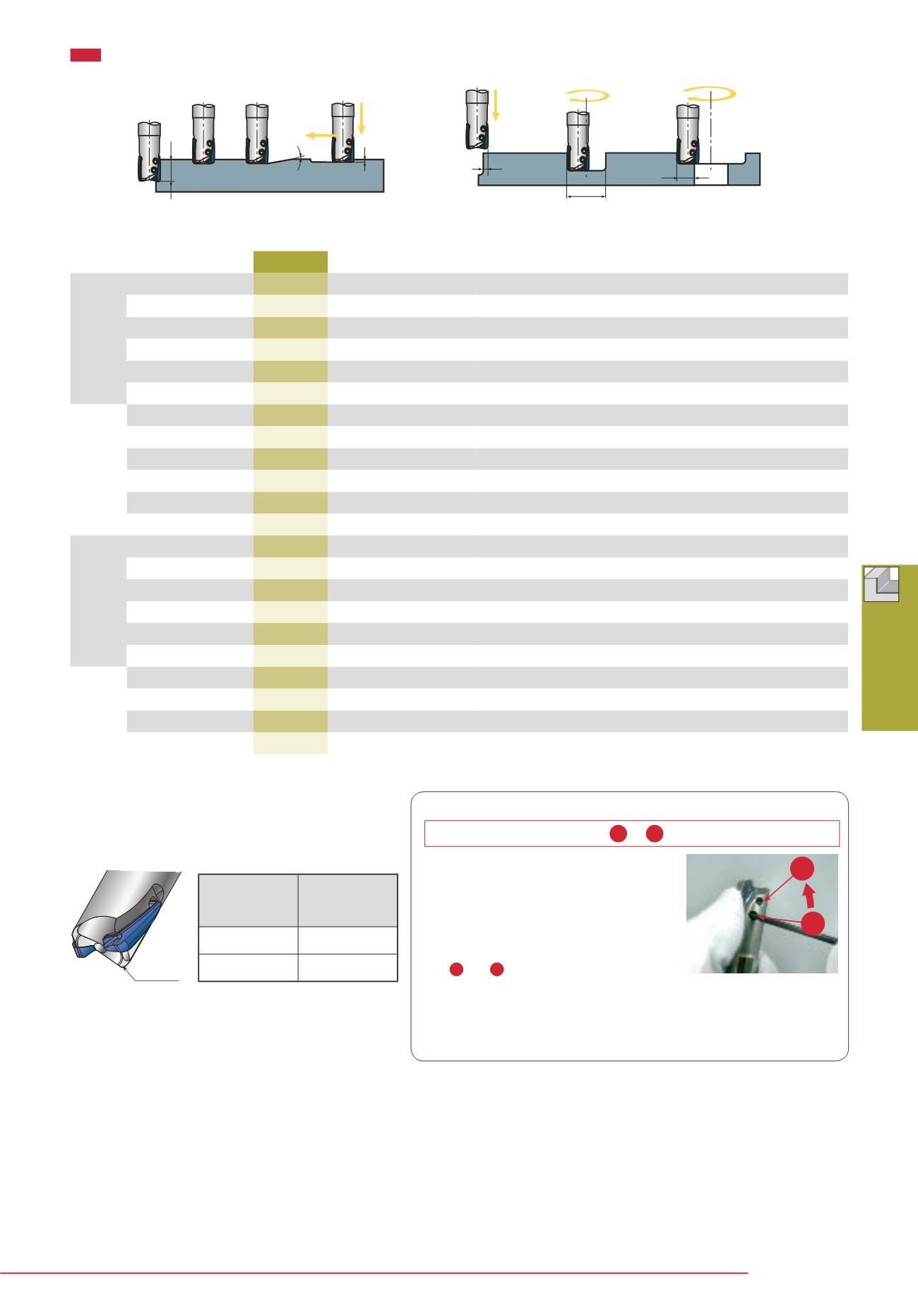
Small
depth
plunging
Ramping
Plunging
Drilling
(Helical feed)
Enlarged
hole
Max. cutting
width in
enlarged hole
Max. cutting
width in
plunging
Max.
machinable
hole ø
Min.
machinable
hole ø
Max. plunging
depth
Max. depth
of cut
Tool ø
Max. ramping
angle


