D056
Shoulder Milling
STANDARD CUTTING CONDITIONS
HB
MJ
HJ
AJ
< 200
AH725
90 - 200
0.05 - 0.1
0.4 - 0.9
-
200 - 300 AH725
90 - 150
0.05 - 0.1
0.4 - 0.9
-
150 - 300 AH725
80 - 120
0.05 - 0.1
0.4 - 0.9
-
-
AH140
90 - 150
0.05 - 0.1
0.4 - 0.9
-
150 - 250 AH725
100 - 180
0.05 - 0.1
0.4 - 0.9
-
150 - 250 AH725
80 - 150
0.05 - 0.1
0.4 - 0.9
-
-
KS15F
300 - 1000
-
-
0.08 - 0.2
-
KS15F
100 - 200
-
-
0.08 - 0.2
-
AH725
20 - 50
0.05 - 0.1
0.4 - 0.9
-
-
AH725
20 - 35
0.05 - 0.08
0.2 - 0.6
-
Feed per tooth: fz (mm/t)
Low carbon steel
C15E4, etc.
High carbon steel and alloy steel
C55, 42CrMo4, etc.
Tool steel
X153CrMoV12, etc.
Stainless steel
X5CrNi18-9, etc.
Grey cast irons
250, etc.
Ductile cast irons
450-10S, etc.
Aluminium alloys
Si < 13%
Aluminium alloys
Si
≥
13%
Titanium alloys
Ti-6Al-4V, etc.
Superalloys
Inconel 718, etc.
· To remove excessive chip accumulation use an air blast.
· To avoid build up edge on the cutting edges (aluminium machining), use a water
soluble coolant.
· When cutting an interrupted surface or a casted skin, the feed per tooth (
f
z) should
be reduced to the lower recommended value shown in the above table.
· Cutting conditions are limited by machine power, workpiece rigidity, and spindle
output. When the cutting width, depth, or overhang length is large, set
V
c and
f
z to
the lower recommended values and check the machine power and vibration.
ISO
Hardness Grade
Workpiece material
CAUTIONARY POINTS WHEN USING HJ INSERTS
R
t
w
10°
r
ε
=
0.8 mm
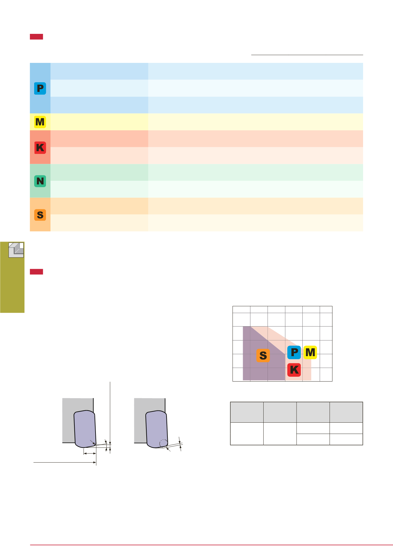
HJ type inserts are designed for high feed machining.
Please note the following when using HJ inserts:
1. The shape of HJ insert differs from that of other inserts (MJ,
AJ). However the same insert pocket can be used.
2. When using HJ inserts, all the inserts on the cutter body
must be HJ type. Do not use other types of inserts (MJ and AJ
types) with HJ inserts on the same cutter body.
3. When using CAD/CAM, please program it as a radius cutter.
The table below shows the corner R when programming and
the uncut area (t).
4. With HJ inserts, the tool diameter increases by 0.6 mm
over the diameter ø
D
c shown in the table.
1.0
0.8
0.6
0.4
0.2
0
0.2
0.4
0.6
0.8
1.0
TungRec 07 type HJ inserts
Standard conditions
Depth of cut:
a
p (mm)
Feed per tooth:
f
z (mm/t)
Steel
Cast Iron
Superalloys
Stainless
Corner R when
programming
Amount left
uncut
0.8
3
R 0.5
0.4
R 1
0.3
Max. depth
of cut
max ap (mm)
Amount left
uncut
t (mm)
Corner R when
programming
Main cutting
edge length
W
(mm)
Max.
a
p: 0.8 mm
Tool diameter:
ø
D
c + 0.6 mm
Cutting speed
Vc (m/min)


