B162
S 0 1 5 3 0
150
125
100
300
200
100
0
75
50
−15º −20º −25º −30º −35º −40º
−15º −20º −25º −30º −35º −40º
W
005
0.05
010
0.10
013
0.13
015
0.15
020
0.20
α
10°
-10°
15°
-15°
20°
-20°
25°
-25°
30°
-30°
35°
-35°
40°
-40°
BXM10 BXM20 BXA20 BXC50 BX310 BX330 BX360 BX380 BX470 BX480 BX910 BX930 BX950
S01325 S01325 S01325 S01325 S01325 S01325 S01325 S01325 T01315 S01325 S01315 S01315 S01325
S01325 S01325 S01325 − S00515 S00515 S00515 − T01315 − S01315 S00515 S00515
2QP-CNGA1204**WL 3QP-WNGA080408WL 2QP-DNGA1504**WJ 3QP-TNGA1604**WG
95°
93°
91°
ACLNR/L**12-A AWLNR/L**08-A ADJNR/L**15-A
ATGNR/L**16-A
ATFNR/L**16-A
DCLNR/L**12 DWLNR/L**08 DDJNR/L**15 DTGNR/L**16
DTFNR/L**16
A**-ACLNR/L12-D... A**-AWLNR/L08-D... A**-ADUNR/L15-D... A**-ATFNR/L16-D...
Insert
PCD / CBN
Turn
L i ne -
T-CBN Ser i es
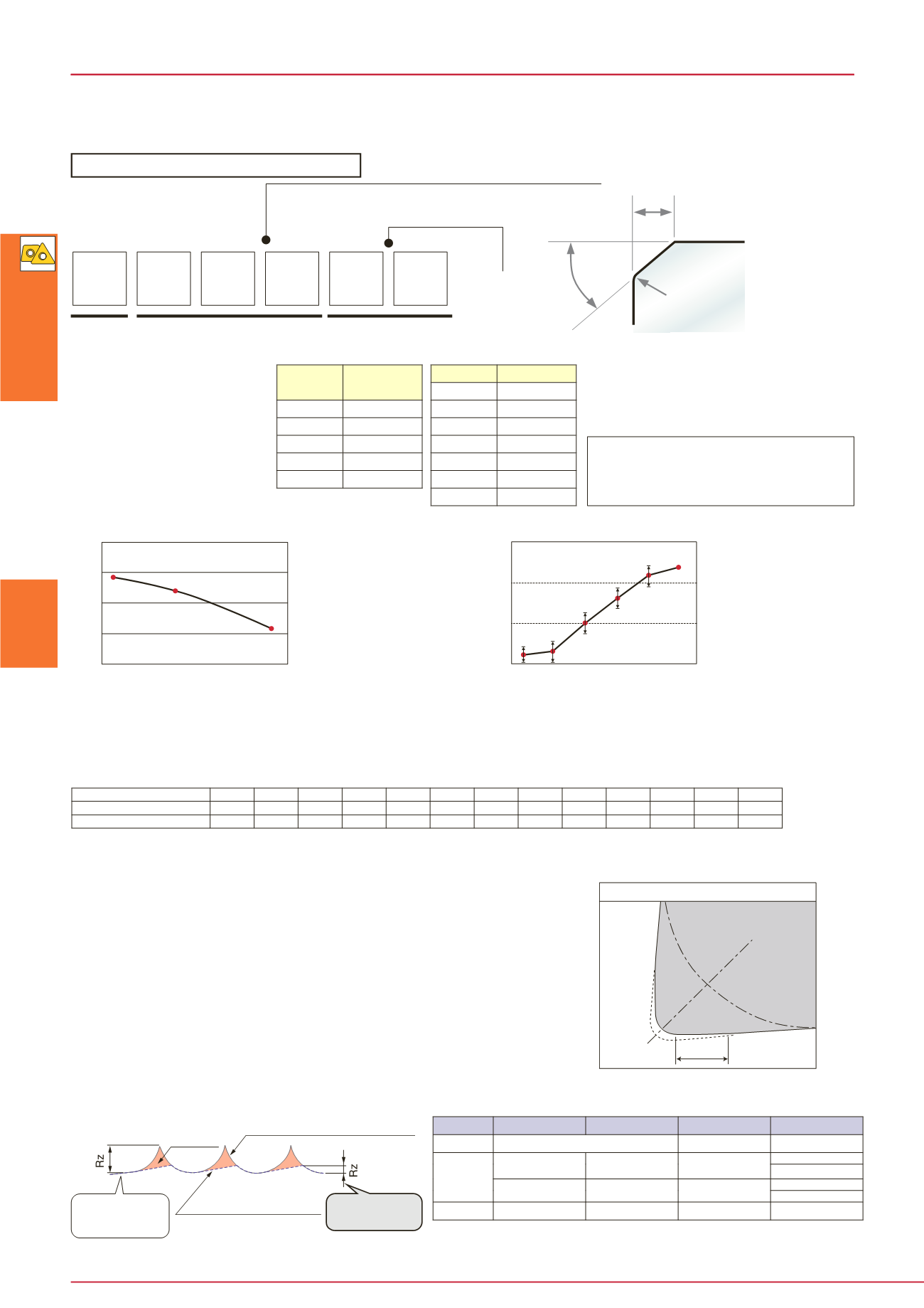
Sectional profile of surface machined
with conventional insert
Sectional profile of
surface machined with
wiper insert
When machining
with conventional
insert
When machining
with wiper insert
Wiper edge geometry
Wiper edge
The wiper edge can double the feed rate and moreover does not deteriorate the
surface roughness. (Note: Feed rate: *
f
< 0.3 mm/rev)
A finishing edge (wiper edge) is formed at the point of intersection
between corner radius and straight cutting edge.
Effect of wiper edge
Superior surface roughness
By integrating roughing and finishing into one
process, productivity can be increased.
Doubles the productivity
Reduced machining time
Compared with conventional inserts only with corner radius, surface roughness
can be improved with the wiper edge.
Profiles of surface roughness
Recommended toolholders for wiper-edged inserts
Time in cut: T (min)
Honing angle
Tool life (%)
Honing angle
T-CBN inserts with special honing specifications are made to order. Refer to the following description.
Honing width W
Example:
Honing width: 0.15 mm
Honing angle: -30°
With R-honing
Shape
T … Chamfered honing
S … Chamfered + R-honing
E … R-honing alone
F … Sharp edge
Honing width (W)
Honing angle (
α
)
Honing angle
α
Rake face
R-honing
Relief face
Honing specification can be selected in combination
of items described here.
Inserts with “R” honing alone are available.
Relationship between honing angle and tool life in continuous turning
General rule
• For
continuous cutting
, small honing angle is favorable to
minimize wear
in general.
• For
interrupted cutting
, large honing angle is favorable to
minimize
fracture
in general.
Symbol
Amount of
honing (mm)
Honing specifications for machining hardened
steel
s and other
hard materials
Honing angle
Relationship between honing angle and tool life in interrupted turning
Cutting conditions
Workpiece material:
Chromium molybdenum
steel
(JIS SCM415), 60 HRC
Insert: TNGN160404 BX360
Cutting speed:
V
c = 100 m/min
Feed:
f
= 0.15 mm/rev
Depth of cut:
a
p = 0.25 mm
Coolant: Dry
Tool life criterion: Fracture
Honing: - °+ R-honing
Wiper inser t
Standard honing: -25° + R-honing
“-L” honing
: -15° + R-honing
“-H” honing
: -35° + R-honing
Cutting conditions
Workpiece material:
Chromium molybdenum
steel
(JIS SCM415), 60 HRC
Insert: TNGN160404 BX360
Cutting speed:
V
c = 100 m/min
Feed:
f
= 0.15 mm/rev
Depth of cut:
a
p = 0.25 mm
Coolant: Dry
Tool life criterion: VBmax = 0.15 mm
Honing: - °+ R-honing
Standard honing specifications
Designation system for honing
Honing spec i f i cat ions
Negative insert
Positive insert
Grades
End cutting
angle
Internal
toolholder
External
toolholder
Removed


