F162
Tooling System
45°
h
1
h
2
β
°
f
α
°
e
1
b
20°
t
øDm
1
16CA 10CA,
12CA
r
ε
L
2
L
1
R
3
45˚
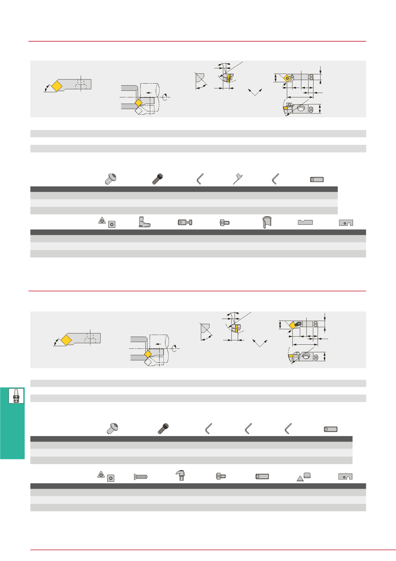
Cutting edge style
S
(Mounting angle)
Inner and external 45° chamfering
(PSSN type is for internal chamfering only)
Square insert
Main application
øDm
2
Right hand (R) shown.
Designation
øD
m1
øD
m2
r
ε
**
f
L
1
L
2
h
1
h
2
b e
1
ℓ
3
β°
α°
t
Insert
PSSNR/L10CA-09
40
55 0.8 14 44 10 10 14.5 10 20
8 -12 0
5 SN**0903...
PSSNR/L12CA-12
50
75 0.8 20 47 12 12 19.5 15 20
8 -12 0
6 SN**1204...
PSSNR/L16CA
55
75 0.8 25 53 28 16 16 17 25
8 -11 0
0 SN**1204...
PN PSSN-CA
Lever lock cartridge with 45° approach angle for negative square insert
b
h
1
h
2
f
e
1
øDm
1
β
°
α
°
20°
t
45°
16CA 10CA,
12CA
r
ε
R
3
L
2
L
1
45˚
Cutting edge style
S
(Mounting angle)
Inner and external 45° chamfering
(PSSN type is for internal chamfering only)
Square insert
Main application
øDm
2
Right hand (R) shown.
Designation
øD
m1
øD
m2
r
ε
**
f
L
1
L
2
h
1
h
2
b e
1
ℓ
3
β°
α°
t
Insert
CSSPR/L10CA-09
40
55 0.8 14 44 11 10 14.5 10 20
8
3
0
5 SP**0903...
CSSPR/L12CA-12
50
75 0.8 20 47 13 12 19.5 15 20
8
4
0
6 SP**1203...
CSSPR16CA
55
75 0.8 25 53 15 16 16 17 25
8
0
0
0 SP**1203...
CP CSSP-CA
Clamp on cartridge with 45° approach angle for 11° clearance square insert
Designation
Shim
Lever
Clamping screw Axial adjusting screw Shim retainer
Sizing plate
Sizing plate ass’y
PSSNR/L10CA-09
-
LCL32N
LCS22
ASM54
-
-
PSTR/L10
PSSNR/L12CA-12
-
LCL43N
LCS43
ASM54
-
-
PSTR/L12
PSSNR/L16CA
LSS42CA
LCL4
LCS4CA
ASM6
LSP4
S0816B/S1016B
-
B47
Designation
Shim
Lever
Clamping screw Axial adjusting screw Radial adjusting screw Chipbreaker piece Sizing plate ass’y
CSSPR/L10CA-09
-
-
CSG-5 (CSG-5S)
ASM54
SSHM4-10
CBS-3M
PSTR/L10
CSSPR/L12CA-12
-
-
CSG-6 (CSG-6S)
ASM54
SSHM4-14
CBS-4M
PSTR/L12
CSSPR16CA
PAS-42
SM3X0.5X8
CSG-8S
ASM6
SSHM5-16
-
-
Notes : Cartridges of K-style cutting edge uses S0816A or S1016A,whilst ones of S-style uses S0816C or S1016B (*marked).
(1)
(1)
(1)
Note: • In above table, øDm
1
is min. bore dia. for axial mounting and øDm
2
is for radial mounting.
• Hand of the insert to be used should be selected depending on the application.
• **r
ε
: Standard corner radius
Note: • In above table, øDm
1
is min. bore dia. for axial mounting and øDm
2
is for radial mounting.
• Hand of the insert to be used should be selected depending on the application.
• **r
ε
: Standard corner radius
SPARE PARTS
Designation
Cartridge setting screw Cartridge setting screw 1
Wrench
Wrench 1
Wrench 2 Radial adjusting screw
PSSNR/L10CA-09
-
CHHM4-4
P-5
P-2F
-
SSHM4-4
PSSNR/L12CA-12
-
CHHM6-25
P-2
P-2.5
P-5
SSHM4-4
PSSNR/L16CA
BHM8-25U
CHHM6-25
P-2.5
P-3
P-5
SSHM5-6
SPARE PARTS
Designation
Cartridge setting screw Cartridge setting screw 1
Wrench
Wrench 1
Wrench 2
Radial adjusting screw
CSSPR/L10CA-09
-
CHHM6-15
P-2
P-2.5
P-5
SSHM4-10
CSSPR/L12CA-12
-
CHHM6-25
P-2
P-3
P-5
SSHM4-14
CSSPR16CA
BHM8-25U
P-2.5
P-4
-
SSHM5-16
(1) Optional
Notes : Cartridges of K-style cutting edge uses S0816A or S1016A,whilst ones of S-style uses S0816C or S1016B (*marked).
When not using Chipbreaker piece, clamping screw in ( ) should be used.
(1) Optional


