F172
Tooling System
øDs
h
f
L
1
L
1
60°
60°
30°
f
h
1
h
1
+5°
+10°
r
ε
Min.bore dia.øDm
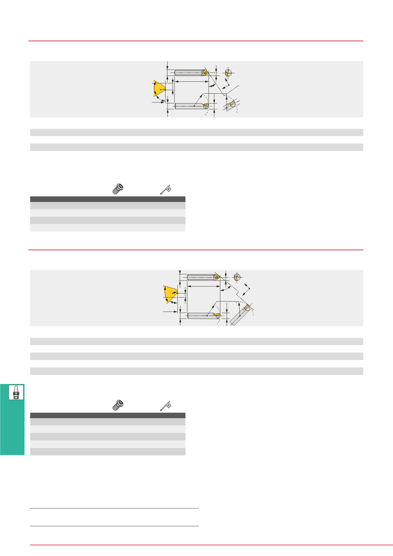
TBR3**T** shown.
Designation
øD
m
f
h
1
h
øD
s
L
1
r
ε
**
Insert
TBR305E04
19
0.5
4
4
5
20
0.2
EP**0401
...
TBR308T08
30
0.5
7
7
8
35
0.2
TP**0802
...
TBR312T11
50
1
10.5
10.5
12
60
0.4
TP**1102
...
TBR316T16
60
1.5
14
14
16
80
0.8
TP**16T3
...
TBR3
30° approarch angle with round shank
Designation
øD
m
f
h
1
h
øD
s
L
1
r
ε
**
Insert
TBR406E04
24
0
5
5
6
25
0.2
EP**0401
...
TBR408T08
30
0.5
7
7
8
35
0.2
TP**0802...
TBR410T09
40
1
8.5
8.5
10
50
0.2
TP**0902...
TBR412T11
50
1
10.5
10.5
12
60
0.4
TP**1102...
TBR416T16
60
1.5
14
14
16
80
0.8
TP**16T3...
TBR4
45° approarch angle with round shank
SPARE PARTS
Designation
Clamping screw
Wrench
TBR305E04
CSTB-2
T-6F
TBR308T08
CSTB-2L
T-6F
TBR312T11
CSTB-2.5
T-8F
TBR316T16
CSTB-4
T-15F
Note: • Figures shown above are of 6 mm or smaller diameter shank used for normal direction of rotation.
• For the tools used for reverse direction of rotation, letter “H” is added in the last position of the Cat. No. (Example: TBR105E04H)
• For the tools for normal direction of rotation, use a left hand insert, and for reverse direction of rotation, use a right hand insert.
• **r
ε
: Standard corner radius
Note: • Figures shown above are of 6 mm or smaller diameter shank used for normal direction of rotation.
• For the tools used for reverse direction of rotation, letter “H” is added in the last position of the Cat. No. (Example: TBR105E04H)
• For the tools for normal direction of rotation, use a left hand insert, and for reverse direction of rotation, use a right hand insert.
• **r
ε
: Standard corner radius
SPARE PARTS
Designation
Clamping screw
Wrench
TBR406E04
CSTB-2
T-6F
TBR408T08
CSTB-2L
T-6F
TBR410T09
CSTB-2.2
T-7F
TBR412T11
CSTB-2.5
T-8F
TBR416T16
CSTB-4
T-15F
h
1
øDs
h
L
1
60°
45°
45°
f
f
h
1
L
1
+5°
+10°
r
ε
Min.bore dia.øDm
TBR4**T** shown.
Inserts for TBR3, TBR4
→
B120 -
(EP**)
, B131 -
(TP**)
,
CBN
→
B168 -,
PCD
→
B178


