F154
Tooling System
b
h
1
h
2
f
L
1
R
3
L
2
e
1
45°
20°
øDm
1
t
β
°
16CA,
20CA
10CA,
12CA
α
°
r
ε
øDm
2
Cutting edge style
F
90°
Shoulder boring
Main application
(Mounting angle)
Right hand (R) shown. 80° rhombic insert used for 06CA.
Designation
øD
m1
øD
m2
r
ε
**
f
L
1
L
2
h
1
h
2
b e
1
ℓ
3
β°
α°
t
Insert
PTFNR/L10CA-11
40
55 0.4 14 50 12 10 14.5 10 20
8
-6 -8
5 TN**1103...
PTFNR/L12CA-16
50
75 0.8 20 55 16 12 19.5 15 20
8
-6 -8
6 TN**1604...
PTFNR/L16CA
55
-
0.8 25 63 23 16 16 17 25
8
-6 -8
0 TN**1604...
PTFNR/L20CA
70
-
0.8 25 70 28 20 20 19 30 10 -6 -7
0 TN**2204...
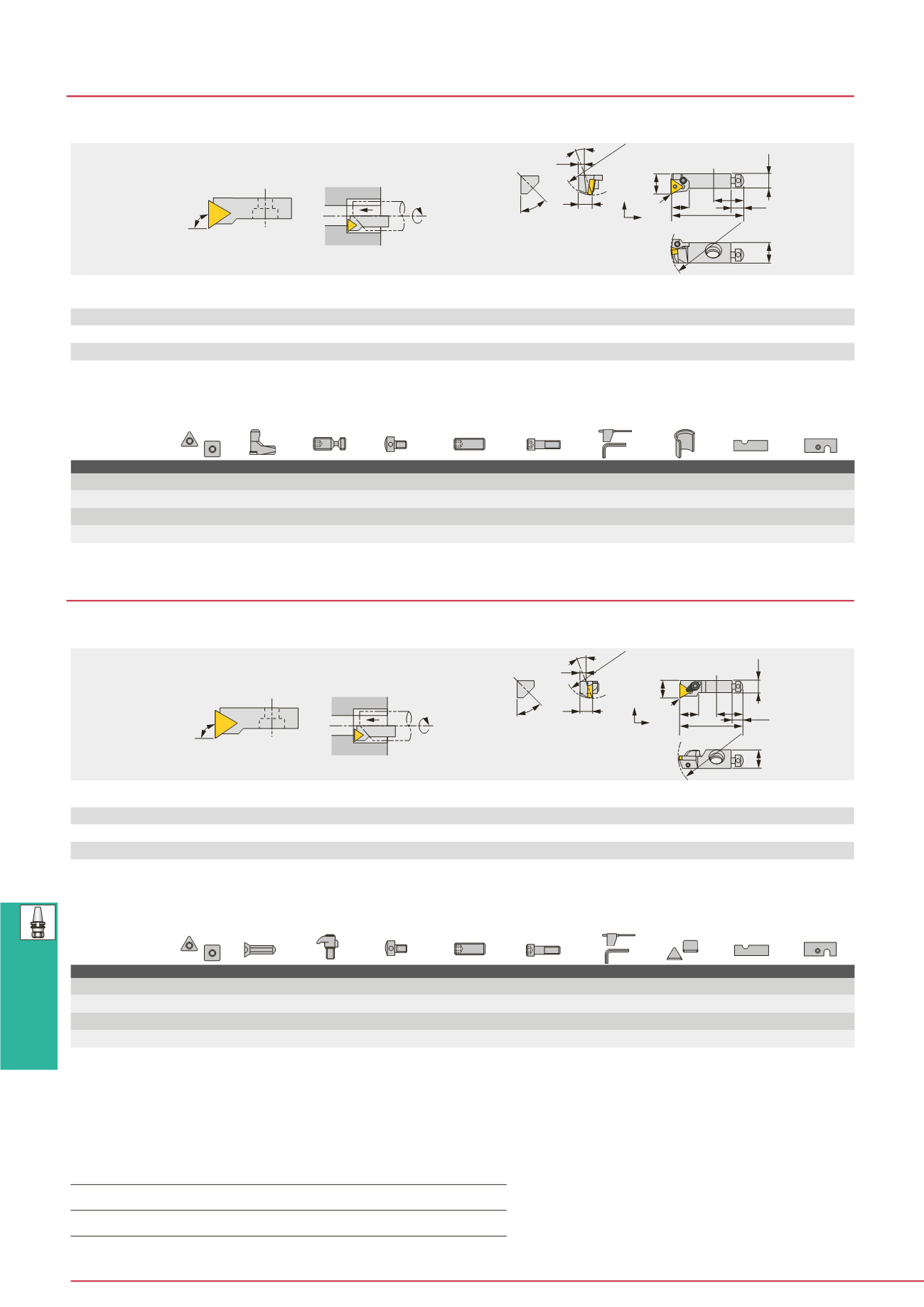
PN PTFN-CA
Lever lock cartridge with 90° approach angle for negative triangule insert
b
h
1
h
2
f
L
1
R
3
L
2
e
1
45°
20°
t
β
°
α
°
16CA,
20CA
10CA,
12CA
r
ε
øDm
2
øD
m1
90°
Shoulder boring
(Mounting angle)
Cutting edge style
F
Main application
Right hand (R) shown.
Designation
øD
m1
øD
m2
r
ε
**
f
L
1
L
2
h
1
h
2
b e
1
ℓ
3
β°
α°
t
Insert
CTFPR/L10CA-11
40
55 0.4 14 50 15 10 14.5 10 20
8
4
0
5 TP**1103...
CTFPR/L12CA-16
50
75 0.8 20 55 17 12 19.5 15 20
8
5
2
6 TP**1603...
CTFPR/L16CA
55
-
0.8 25 63 23 16 16 17 25
8
5
0
0 TP**1603...
CTFPR/L20CA
70
-
0.8 25 70 22 20 20 19 30 10
5
0
0 TP**2204...
CP CTFP-CA
Clamp on cartridge with 90° approach angle for 11° clearance triangle insert
Note: • In above table, øDm
1
is min. bore dia. for axial mounting and øDm
2
is for radial mounting.
• When using a right or left hand insert, the right hand insert is used for left hand toolholders and the left hand insert is used for right hand toolholders.
• The left hand insert is used for the right hand cartridge and right hand insert is used for left hand cartridge.
• **r
ε
: Standard corner radius
Note: • In above table, øDm
1
is min. bore dia. for axial mounting and øDm
2
is for radial mounting.
• When using a right or left hand insert, the right hand insert is used for left hand cartridge and the left hand insert is used for right hand cartridge.
• The left hand insert is used for the right hand cartridge and right hand insert is used for left hand cartridge.
• **r
ε
: Standard corner radius
(1) Optional
SPARE PARTS
Designation
Shim Lever
Clamping screw Axial adjusting screw Radial adjusting screw Cartridge setting screw Wrench Shim retainer Sizing plate Sizing plate ass’y
PTFNR/L10CA-11
-
LCL22N LCS22
ASM54
SSHM4-4 CHHM6-15 P-2F,P-5
-
-
PSTR/L10
PTFNR/L12CA-16
-
LCL33N LCS33
ASM54
SSHM4-4 CHHM6-25 P-2F,P-5
-
-
PSTR/L12
PTFNR/L16CA LST317CA LCL3
LCS3
ASM6
SSHM5-6 BHM8-25U P-2.5,P-5
LSP3 S0816B/S1016B
-
PTFNR/L20CA LST42CA LCL4
LCS4
ASM6
SSHM5-6 BHM8-30U P-2.5,P-3,P-5 LSP4 S0820B/S1020B
-
B47
(1)
(1)
SPARE PARTS
Designation
Shim
Lever
Clamping screw Axial adjusting screw Radial adjusting screw Cartridge setting screw Wrench Chipbreaker piece Shim retainer Sizing plate ass’y
CTFPR/L10CA-11
-
-
CSG-5 (CSG-5S)
ASM54
SSHM4-10 CHHM6-15 P-2,P-2.5,P-5 CBT-2M
-
PSTR/L10
CTFPR/L12CA-16
-
-
CSG-6 (CSG-6S)
ASM54
SSHM4-14 CHHM6-25 P-2,P-3,P-5 CBT-3M
-
PSTR/L12
CTFPR/L16CA PAT-32 SM3X0.5X8 CSG-8S
ASM6
SSHM5-16 BHM8-25U P-2.5,P-4
-
S0816B/S1016B
-
CTFPR/L20CA PAT-42 SM3X0.5X8 CSG-8
ASM6
SSHM6-16 BHM8-30U P-3,P-4
-
S0820B/S1020B
-
Notes : Cartridges of K-style cutting edge uses S0816A or S1016A,whilst ones of S-style uses S0816C or S1016B (*marked).
When not using Chipbreaker piece, clamping screw in ( ) should be used.
(1) Optional
Inserts for PN PTFN-CA
→
B079 -,
CBN
→
B164 -,
PCD
→
B176
Inserts for CP CTFP-CA
→
B131 -,
CBN
→
B168 -,
PCD
→
B178


